HW-16 Complete Rebuild
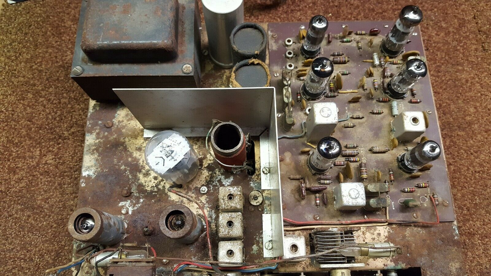
The copper-clad chassis was a rusty mess and the PC board was very dirty. This HW-16 appears to have been kept in a very damp environment, possibly a damp basement or a damp storage location. The 6GE5 tube had a cracked glass envelope causing the Barium coating on the inside wall of the tube to turn White. I ordered and received replacement 6GE5s. The other tubes appear to be in good shape. I need to test them to see if they have simple conductive current flow and filament lighting. During disassembling/removing components from the chassis, I damaged the 9-pin tube sockets beyond repair. The socket mounting screws were rusted and simply would not come off. I have 2 new 9-pin tube sockets to replace the original socket. The 12-pin final socket was easy to remove so it was saved and cleaned up for use. The small transformers had some corrosion and I was able to remove most of the corrosion with steel wool. The mounting clips had rust which I could not remove even with a wire brush but they were kept for reuse. The “L” shield was removed and cleaned. It’s made of “Aluminum” which doesn’t sit well with “copper”. I thoroughly cleaned it for reuse. The final tank coil was removed and checked using my LCR meter against a known good tank coil. The checks were good. I removed the original tank coil connecting wires and replaced them with #16AWG solid copper magnetic wire. I cut the wires to the required length, stripped the coating on each end, and connected and soldered each wire to the tank coil. I did not separate the lower 15-meter windings, I left the windings as they originally were. The receiver’s variable capacitor was removed and cleaned. The ball bearings were cleaned and lubricated with DeoXit L260 grease. The capacitor frame has a small amount of rust which could not be removed with a wire brush. The capacitor itself, when tested with my LCR meter, was tested satisfactorily.
=============================================================================
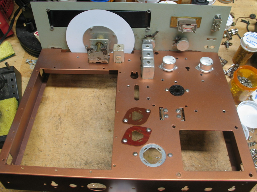
The restored copper-clad chassis with a few components mounted. I sanded the top and bottom of the chassis then applied a coat of primer filler. The rust created “pits” that would make the restored chassis look bad. To fix the rust pits I applied a coat of primer filler then I applied a coat of Rustoleum Metallic Coopper paint. The chassis turned out very nice. The original dial broke when removing it from the mounting plate. I found a new reproduction dial on eBay. I cleaned up the small transformers and other components saved during disassembly. The 2 insulated can capacitor mounts are new. The metal can capacitor mount is original, it was cleaned, hammered flat, and reused. The receiver RF gain and transmitter output pots were cleaned and checked for reuse. The slide switch was cleaned and checked for reuse. The large FT-243 crystal socket broke so I found a replacement. The smaller HC-6/U crystal socket was cleaned and reused. The front panel was cleaned with mild soap and water. I learned from a previous HW-16 restoration to not use a harsh “Simple Green” cleaner which damaged the front panel silk screening. The meter clamp was broken on one end. I soldered the break and it appears to be holding the meter on the panel.
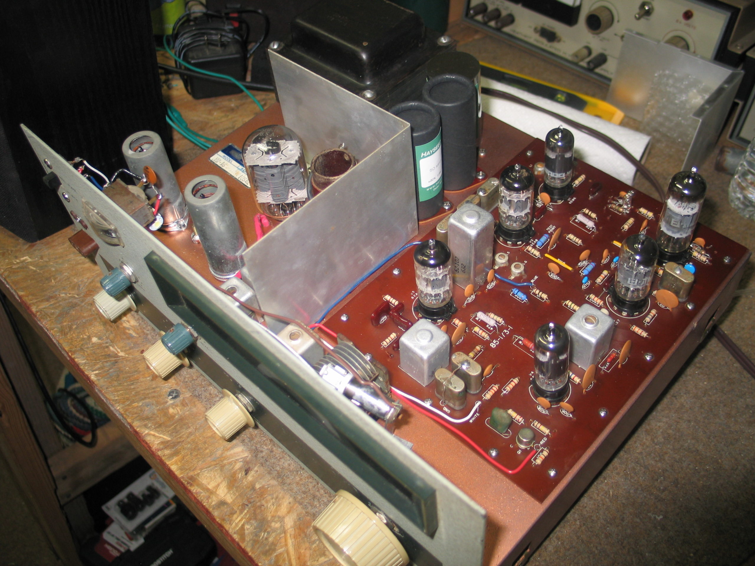
Top view
The power transformer was cleaned and each winding was DC resistance checked against a known good HW-16 power transformer. No shorts to the core and between primary and secondary windings were found and the resistance of each winding was within a couple of ohms when compared to the known good power transformer.
![]()
==============================================================================
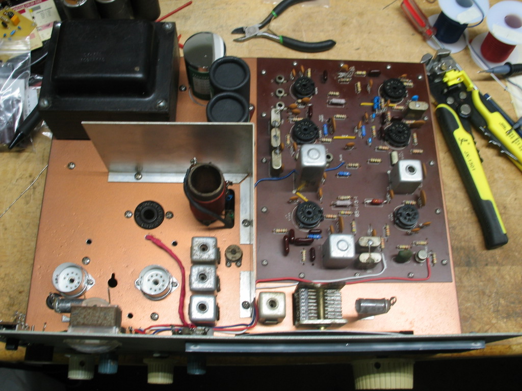
The power transformer along with other mechanical components were installed on the chassis.
The “L” bracket is aluminum. Aluminum and copper when they come in contact with one another, corrosion occurs where the two metals touch. To help prevent corrosion between the shield and the copper chassis, I used four #6-star lock washers sandwiched between the shield and the chassis on each of the four mounting screws, washers, and nuts.
I spent a lot of time cleaning up excess amounts of solder used by the original builder or previous owners. Once that was completed, the board was rebuilt with all new resistors and capacitors. The board was mounted to the chassis with all new mounting hardware. Once the board was mounted, I checked for ground continuity at various ground foil areas on the PC board and the chassis grounds. All tests were successful. I used a large drill bit and “manually” rotated the bit around each mounting hole both on the top and bottom of the chassis. This removed the paint from around the “edge” of each mounting hole allowing the “star lock washer” to bite into and make a solid metal-to-metal connection. Each mounting screw, ground lug, and ground terminal strips were tested for continuity throughout the chassis. All tests were successful. The ground foil run around the bottom of the PC board was scrubbed with steel wool then each mounting hole was cleaned of paint using the large manually rotated drill bit on each hole. I added a #3-star lock washer between the PC board foil side and the chassis. This allowed for a solid foil to chassis connection. Once the board was installed a thorough test for continuity from the board’s ground foil runs on the bottom of the board to all ground points on the top and bottom of the chassis. All tests were successful. The dial lamp holders were scrubbed clean using a Dremel wire brush tool. I cleaned the inside of the lamp socket with a cotton swab wet with DeoXit D5 cleaner. The large drill bit was manually rotated around the top and bottom of the lamp mounting holes. The lamp sockets were then mounted to the chassis using a 6x32x1/4″ machine screw, #6-star lock washer, and 6x32x1/4″ machine nut. The lamp holders to chassis ground connections were checked at various locations on the chassis and found to be very good.
The Hayseedhamfest capacitors and resistor kit arrived. The capacitors were mounted to the chassis and point-to-point chassis wiring began.
========================================================================
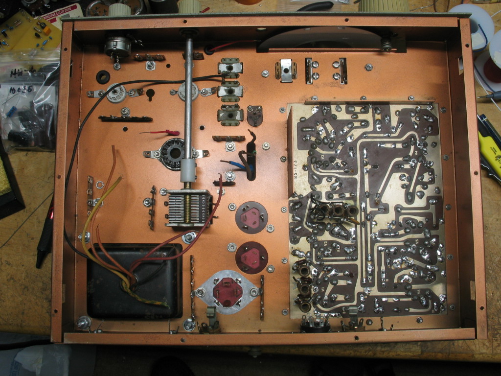
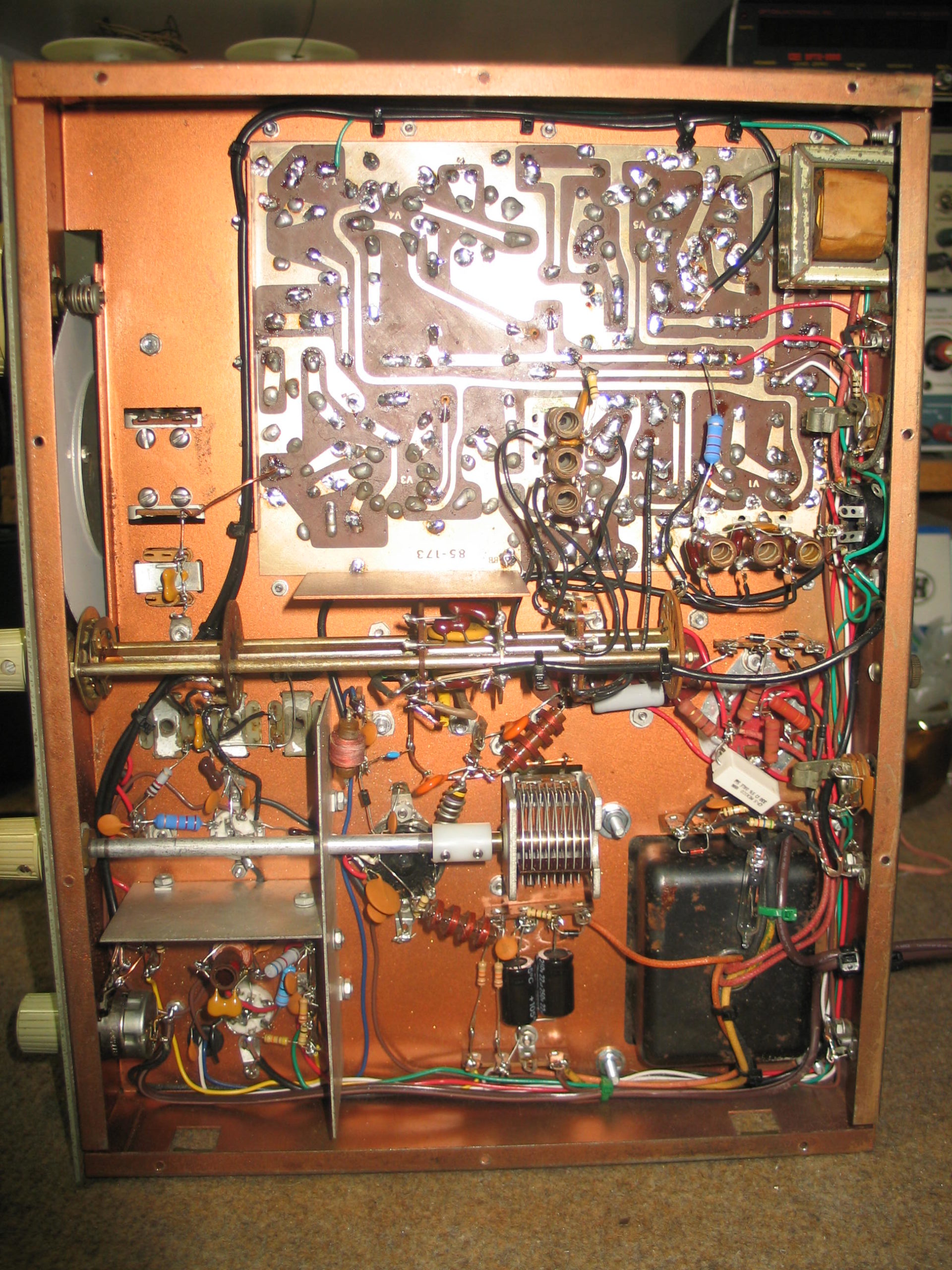
Below chassis view.
=========================================================================
Completed Copper clad chassis HW-16 full restoration
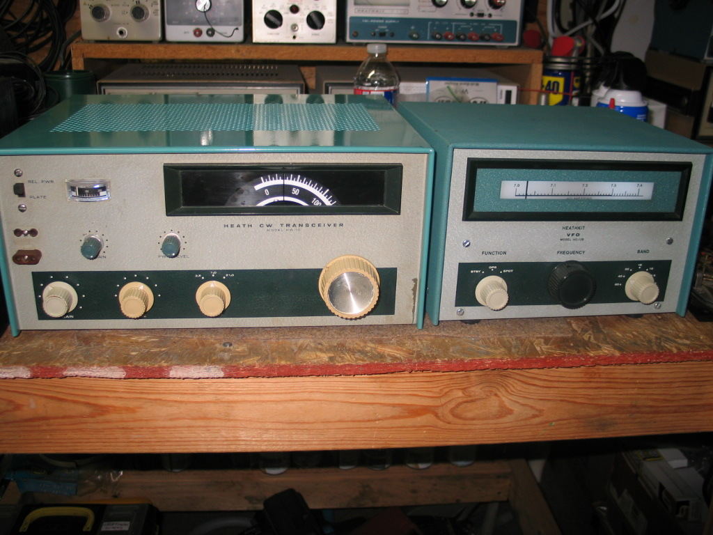
Front view with HG-10 VFO.
The first station I worked on 40 meters gave me a 589 report, no drift, and no chirp. The initial receiver dial was off by 20Khz. I used a frequency counter connected to the HG-10 VFO output at 7.0. I tuned the receiver to 7.0 and adjusted the VFO coil for a zero beat. I checked at 50 and 100 on the dial and they were within acceptable dial calibration.
HW16 Copper Clad chassis operating Video
=========================================================================
Inside top view of completed full restoration. I replaced the original #47 dial lamps with BA9 Mini-Bayonet-based 6V LED lamps. The dial is new, obtained on eBay for $19.95. The power supply filter capacitors are from hayseedhamfest.com including the 2 insulated 50ufd 450VDC capacitors. All the mounting hardware is new. The Oscillator V7, Driver V8, and final amplifier V9 tube sockets are new. The “L” shape shield is held “OFF” the chassis by four #6-star lock washers between the chassis and the shield mounting hardware. The final tube is NOS, original tube had a crack in the glass envelope. The two 6CL6 tubes are original, the tubes on the PC board are original except for the BFO/Product Detector (12AX7) which I replaced, which was weak. The alignment was already good. Had two initial problems, REL PWR and PLATE meter indications failed? REL PWR meter failure was caused by an open RF choke. The PLATE meter failure was caused by bad connections to the band switch wafer and the final tank coil. Fixed that and both REL PWR and PLATE meter indications are working. Power output is 50 watts on 80 and 40 and approximately 35 watts on 15 metes. I didn’t spread the bottom windings on the tank coil for full output. When I restore a device/item I restore it to its original design. I did not make any modifications other than dial lamps.
=========================================================================
Inside bottom view. All wiring and coax cables are new. All mounting hardware is new. The TUNE coupler was replaced, the original coupler would not slide off the shaft, I had to cut it with a box cutter. The new coupler is made out of 3/4″ long 1/2″ diameter by 1/4″ bore. I drilled 2 holes, one on each end, and taped the holes to accept the #8×1/4 hex set screw. The last step I have to complete is to create the decals for the rear apron sockets and connectors. I’ll get to those a little later on. For now, the HW-16 is working as it was originally designed.
===============================================
==============================================
============================================
==========================================
=========================================