Heathkit HR-1680 & HX-1681
I finally got around to working on the HR-1680 and HX-1681 twins. They both have sat around for too long.
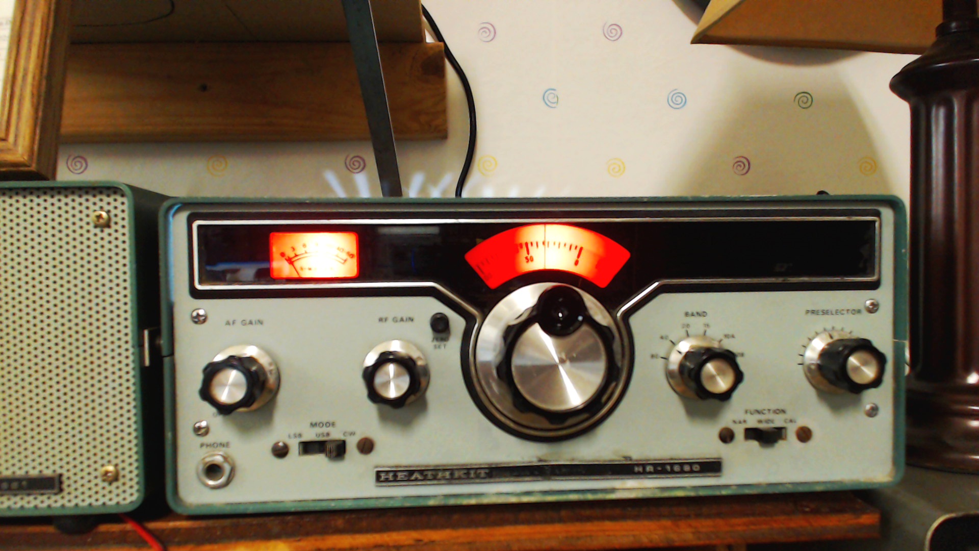
First the HR-1680 receiver. I replaced the HR-1680 power supply 1500ufd 50VDC filter capacitor and cleaned the individual board plug-in pins and sockets with D5 contact cleaner. I also performed Heathkit’s recommended changes if the HR-1680 is used with the HX-1681 (see HX-1681 assembly manual page 108 for details). I also replaced the high current 12V dial lamps with 12V LEDs. The LEDs produce more light and draw less current from the already overstressed 12-volt regulator. The “White” on the meter and the dial is glare from the overhead fluorescent light not from LED light bleed through. The receiver works great on all bands, very stable and quite sensitive.
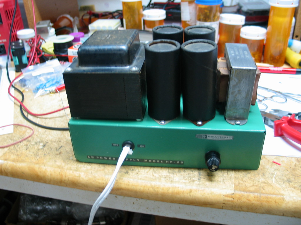
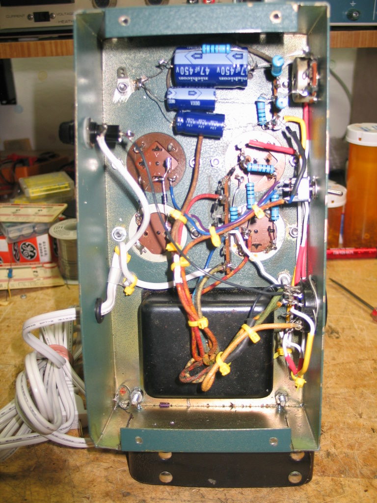
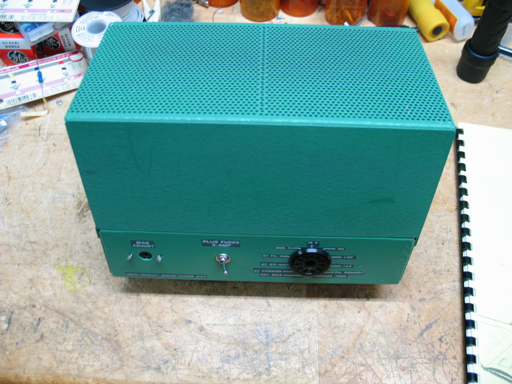
Now for the scratch built HP-23A power supply. The HX-1681 11 pin power connector normally has an 11 pin male connector on the rear panel. However, for some reason, the builder installed an 11 pin female socket so the power cable was made with male plugs on both ends. The power supply was already built, tested, and found to have proper AC filament, bias, LV, and HV DC voltages. A 3 wire power cord, not shown in the picture below, has since replaced the 2 wire polarized power cord.
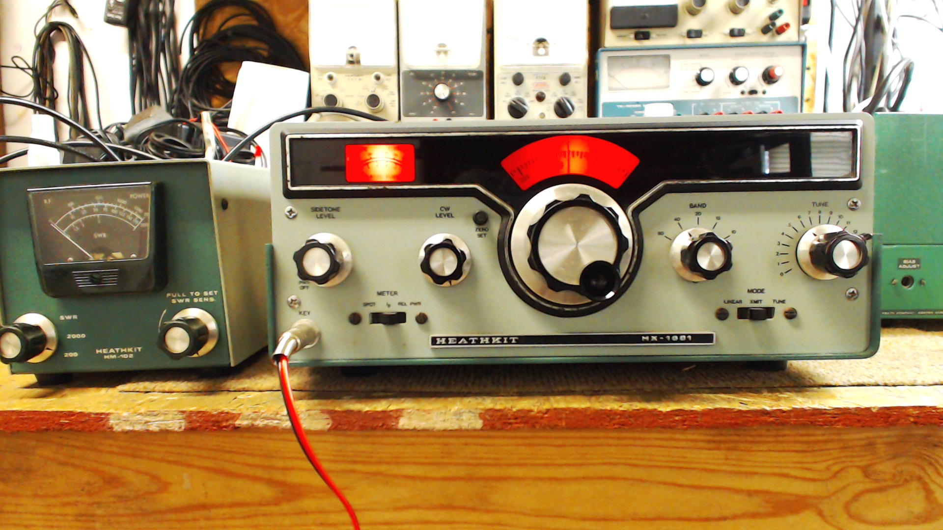
Now the HX-1681 transmitter. Front view of the HX-1681 with the top removed for testing. Initial manual resistance checks passed. Power-up tests went without any problems. Initial power output tests showed max power output was 50 watts. The driver (12BY7A) and both final tubes (2 x 6146A) are known good tubes recently purchased tubes from vacuumtubes.net. The only possible source of low power output could be the HET OSC/MIXER board. The HET OSC/MIXER board produces the actual transmit RF signal that is fed to the driver stage. A low RF output signal from the HET OSC/MIXER board results in low RF output from the driver and ultimately the final amplifier. I swapped the board with a spare and now max power output is 100W on 80-15 and about 80W on 10. I noticed the VFO output was off by 30Khz. The solution was to connect a frequency counter to the VFO output then adjust the VFO coil about 1/2 turn so the VFO output at the bottom of the dial is 5.5Mhz and 5.0Mhz at the top of the dial. No further problems were found so the top cover was replaced.
============================================
HR-1680 and HX-1681 Twins
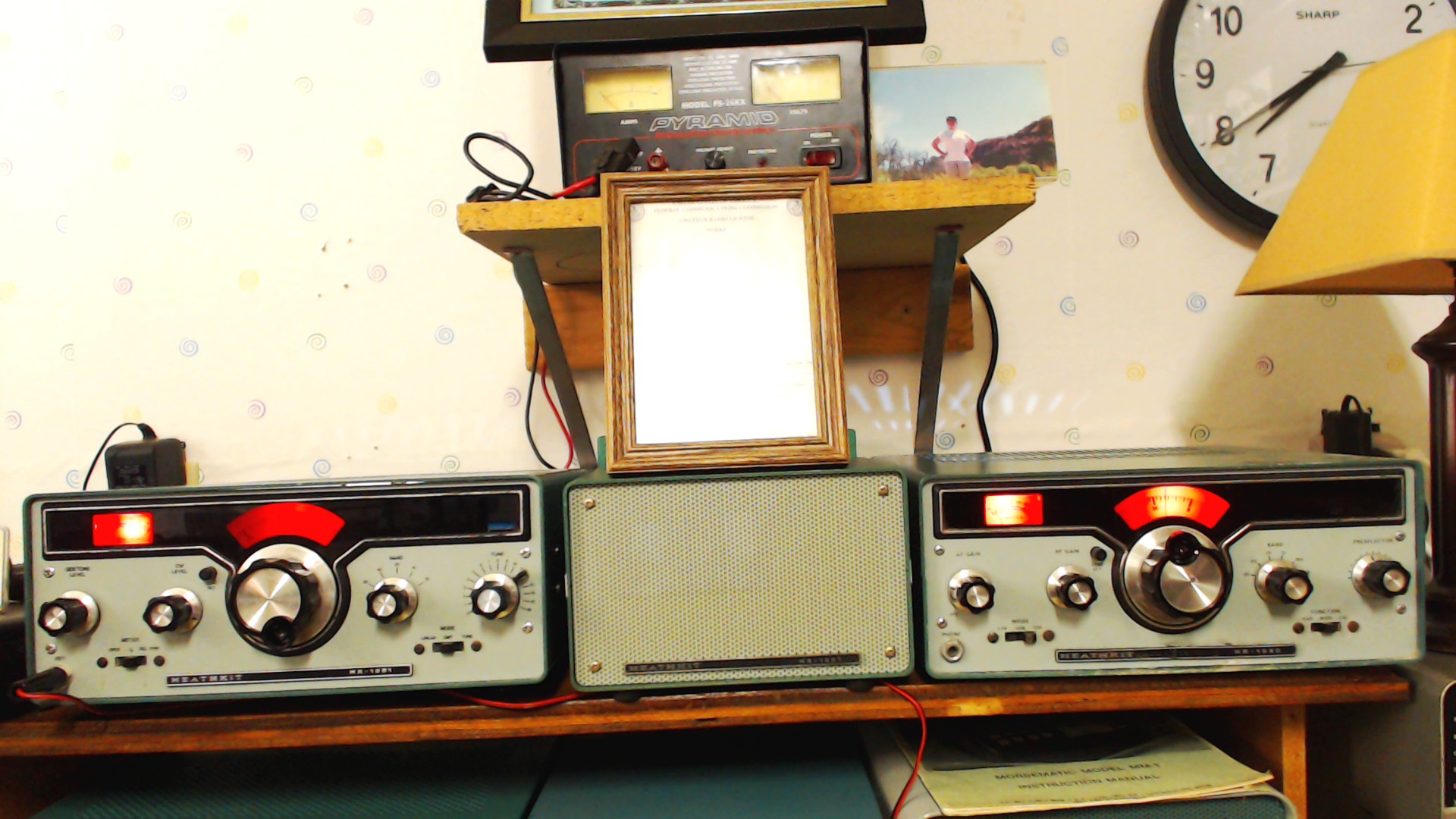
Since all initial tests had passed, I connected the HR-1680 and HX-1681 and HS-1661 with interconnecting MUTE, SPKR, SIDETONE, and ANT cables. I did find a significant level of hum in the speaker with the transmitter connected to the receiver. I checked all grounds, including the HP-23A supply and power cable, no faults were found. I noticed by disconnecting the SIDETONE interconnecting cable the hum disappeared. Disconnecting either the MUTE or ANT cables did not eliminate the hum. There also were no changes in the hum after checking/tightening all grounds etc. It was determined the hum was caused by the SIDETONE connection between the receiver and transmitter. I solved the hum problem by breaking the sidetone output connection in the transmitter at the sidetone output socket and inserting a 0.001ufd disc cap in series with the sidetone output and sidetone socket. This eliminated the hum completely. I adjusted the sidetone frequency to a more acceptable tone and adjusted the LINEAR delay pot for a 2-second delay. QSK keying works great just like the QSK keying in my HW-16’s.