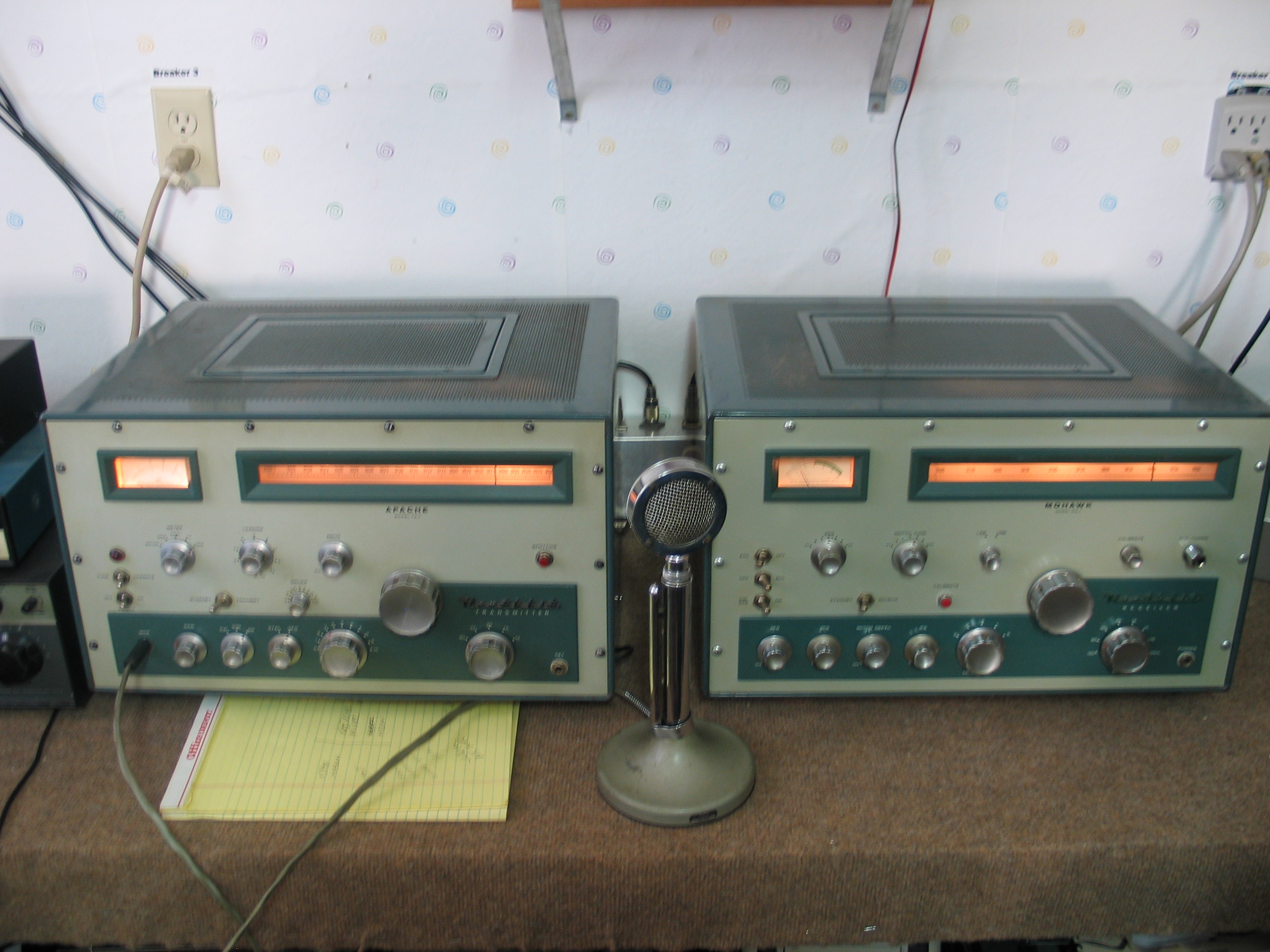
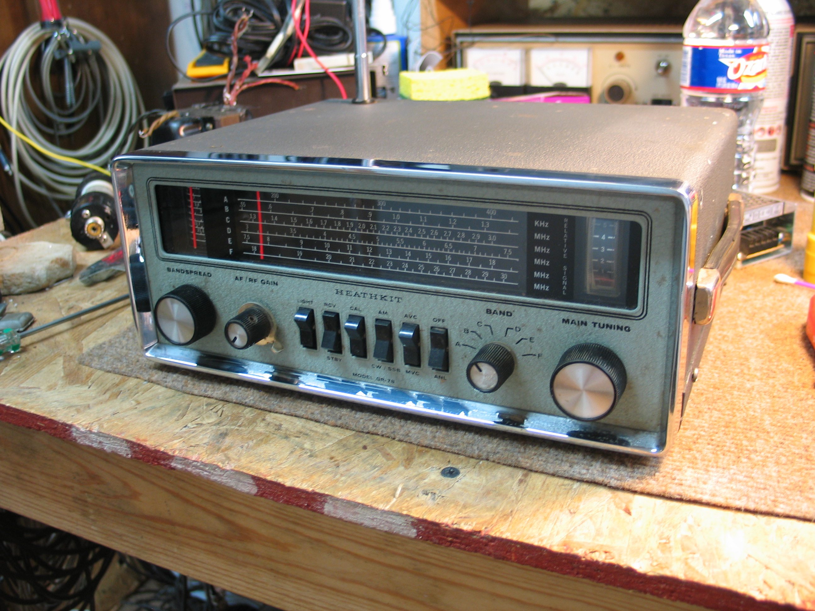
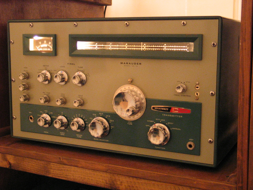
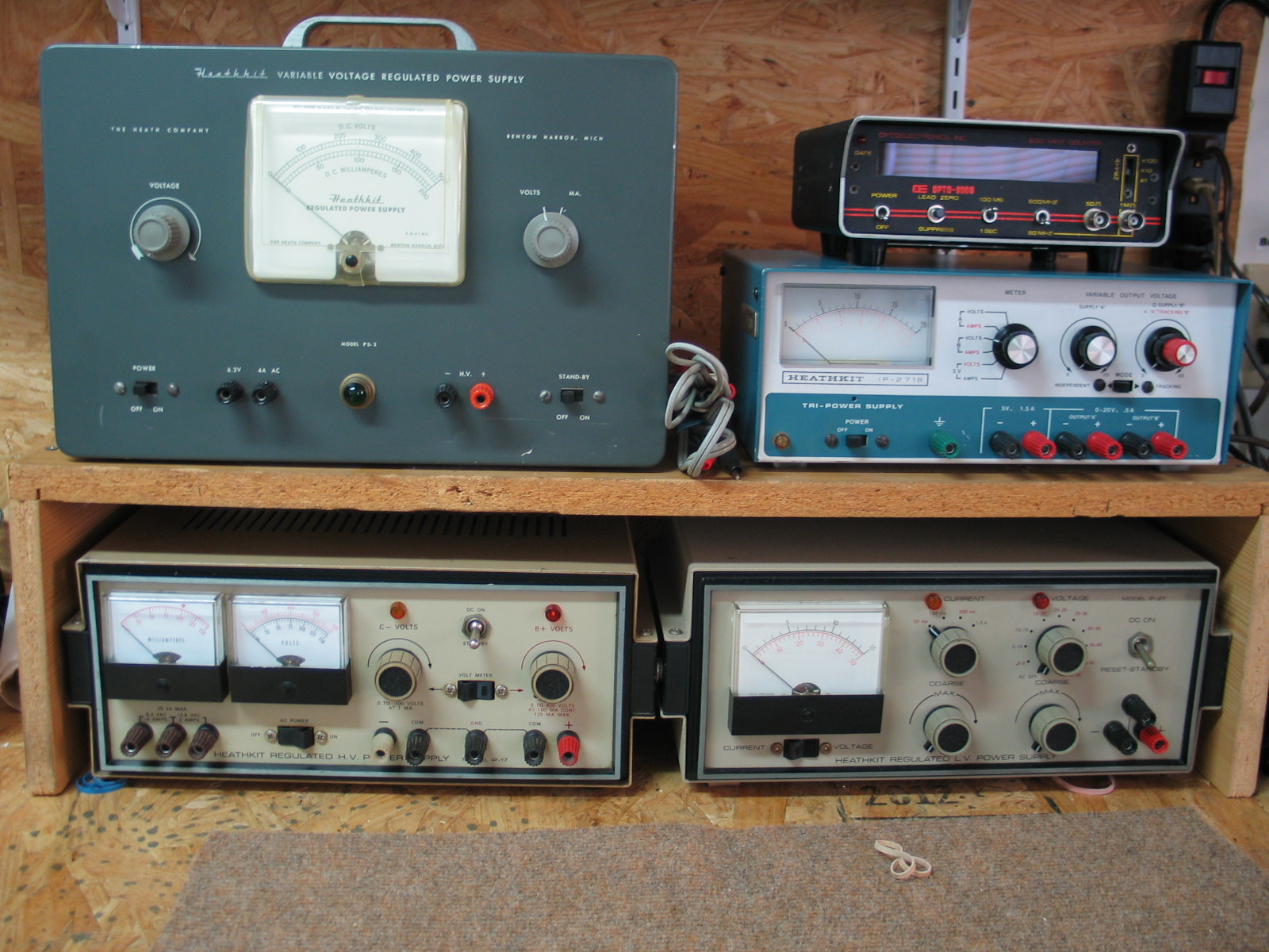
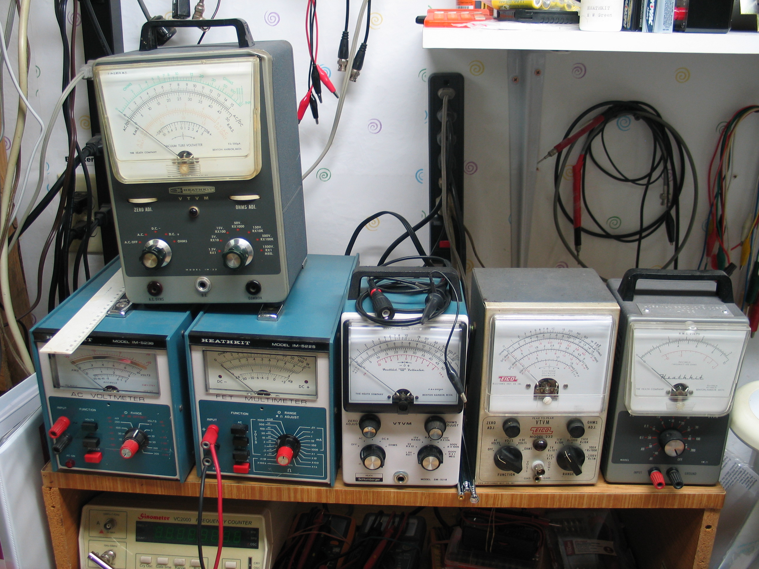
Heathkit Collection
===========================================================================
DX-60 Function Switch Simple HV Relay Mod
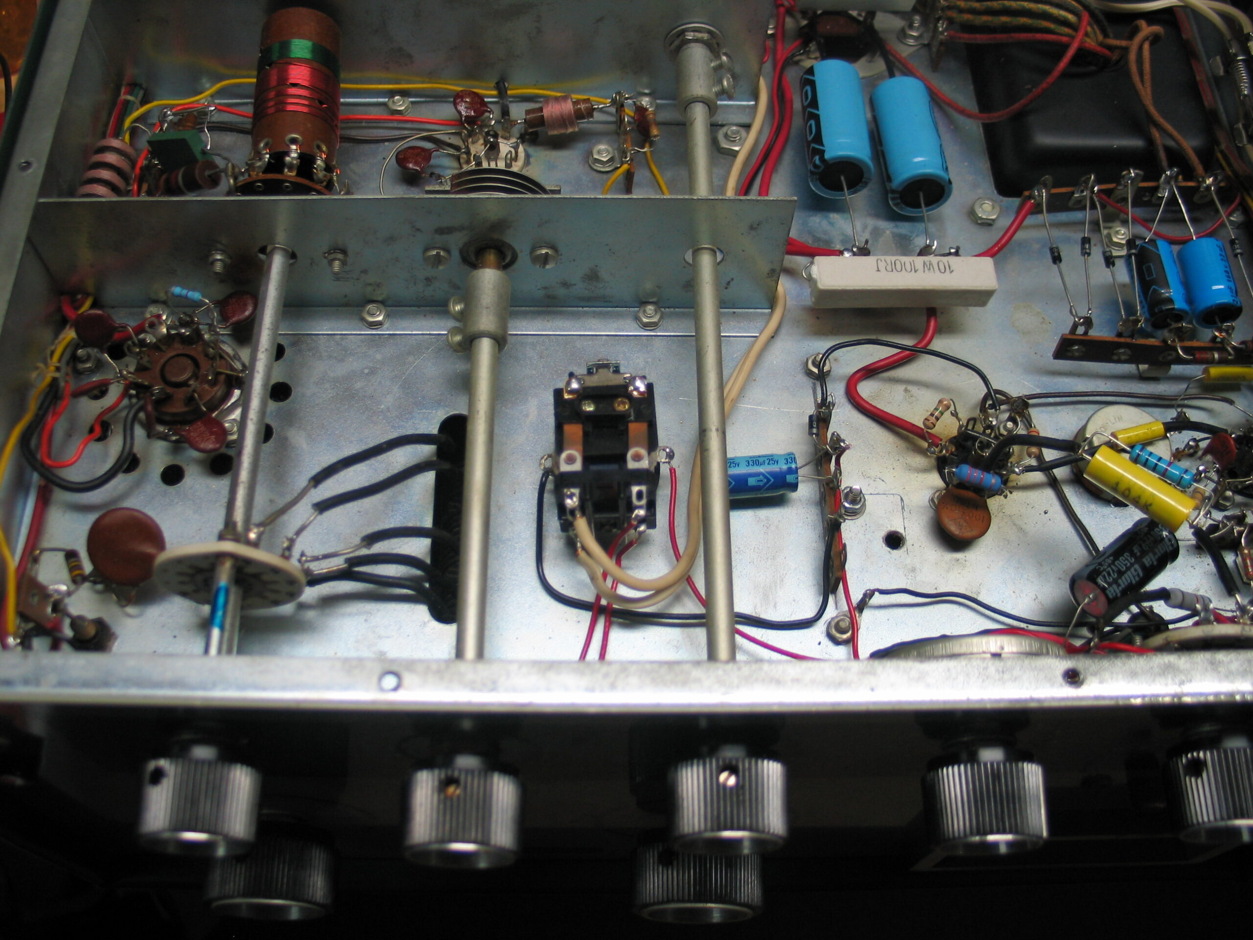
The relay I used is a 6VDC DPDT open frame relay with a 6x32x1/4″ threaded stud on the relay armature. A *small hole is drilled to mount the relay below the chassis. I added a small rubber grommet over the relay coil’s threaded mounting stud to help reduce the noise creased when the relay energizes.
Whether this relay is used or another relay mounted with double stick Velcro tape, is entirely up to the user. I don’t like using tape as heat can cause the tape adhesive to soften.
The multi tab terminal strip is mounted using one of the final amplifier enclosure 6×32 mounting stud nuts. That terminal strip mount also serves as “Ground” for one terminal of the relay coil and the half wave rectifier capacitor’s negative terminal.
The relay consists of 2 sets of “SPDT” switches. Only one set of SPDT contacts are used.
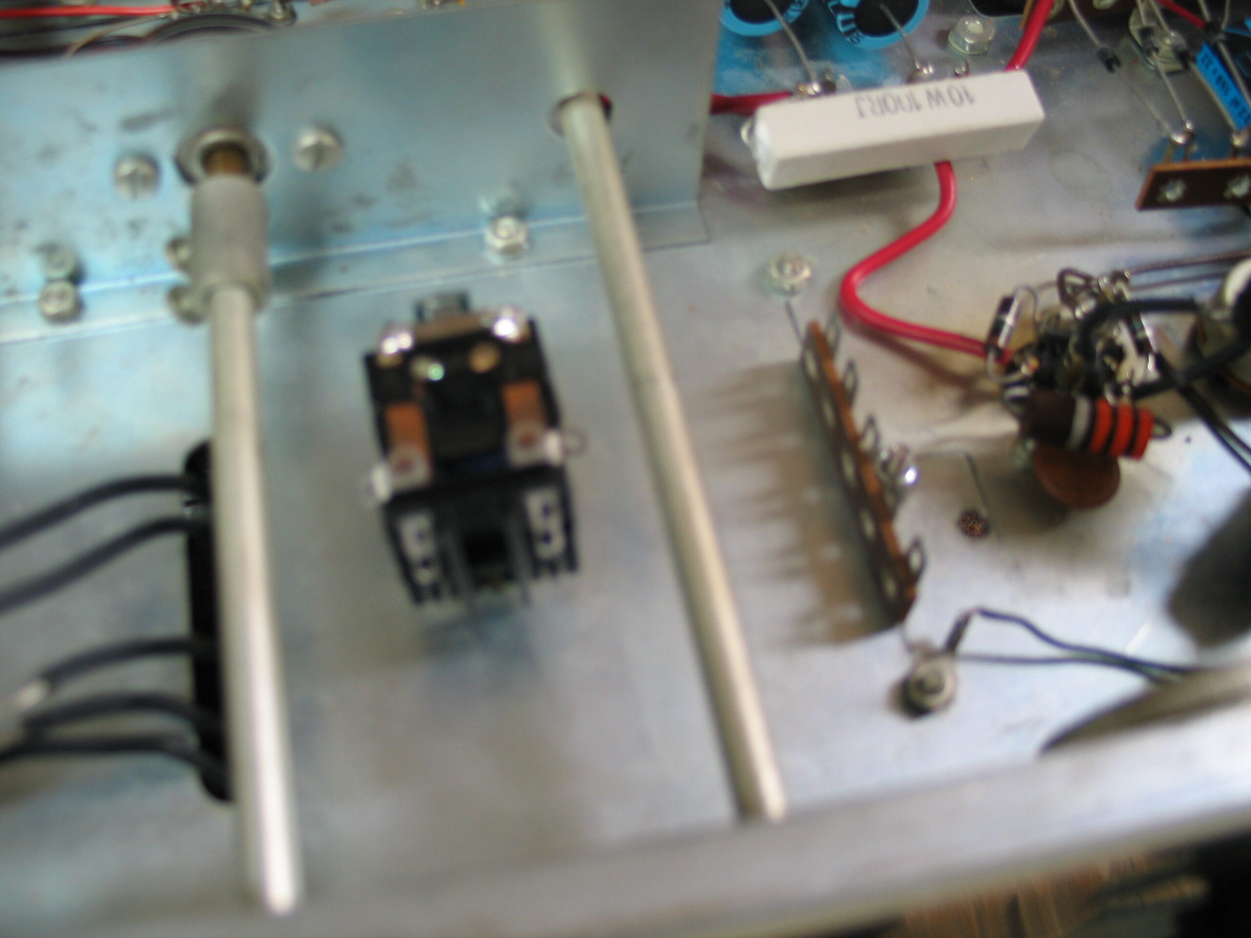
A wire taps V4 pin 4 to provide 6VAC filament voltage to the half wave rectifier.
The half wave rectifier circuit is mounted on the terminal strip and consist of a single diode (1N4007, I have a lot of these) and a 300ufd 50VDC filter capacitor. The filter capacitor must be a high capacitance value capacitor in order to prevent the relay from “Chattering” when energized in TUNE, PHONE, or CW modes. If the relay chatters when energized then the capacitor value is too low, increase the value of the capacitor’s capacitance value until the relay no longer chatters when energized.
The 2 Red wires from the Function switch terminals 4 and 5 are removed from the Function switch and reconnected to one set of the relay’s “N.O.” contacts.
“N.O.” is short for “Normally Open”.
The DC output of the half wave rectifier connects to terminal “4” on the Function switch. Terminal 5 of the Function switch connects to one terminal of the relay coil. The other relay coil terminal connects to the terminal strip Ground. This completes the Function switch relay installation.
The Function switch now switches only “6VDC” rather than the 260VAC in TUNE, PHONE, and CW modes. This has worked very well and does not result in any negative affects to the tube’s filament voltage.
The picture below shows a “White” wire routed from the relay to an additional RCA socket on the DX-60 rear apron. This is not required to complete the Function switch relay installation so ignore that wire.
===========================================================================
HG-10 / VF-1 Power Supplies
I designed a PC board for 2 separate power supplies mounted on a small BUD chassis. The Hammond power transformer and HP-23 choke on the left is for the VF-1 supply and the Hammond power transformer on the right is for the HG-10 power supply.
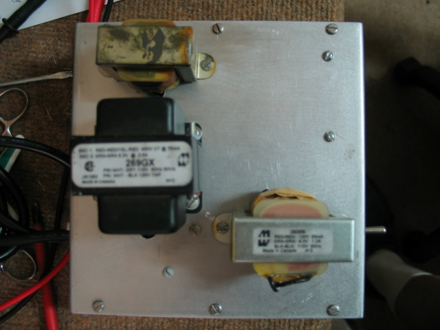
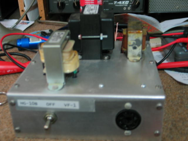
The 3 position toggle switch is from a Heathkit HP-23 power supply. The switch selects the desired power supply output at the octal socket on the right. Switch setting to the left selects the HG-10 supply output, Switch center setting turns power OFF, and switch setting to the right selects the VF-1 supply output.
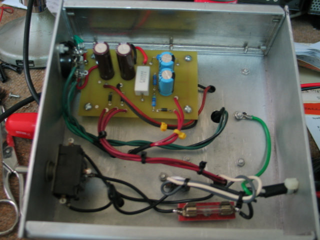
Dual power supply PC board mounted below the chassis using dual 6x32x3/8 female hex stand-offs. Power supply section on the right is for the HG-10 built from the HG-10 manual schematic Figure 4 page 29 and the power supply on the left is for the VF-1 supply.
===========================================================================
HW-100 and HW-101 LMOs
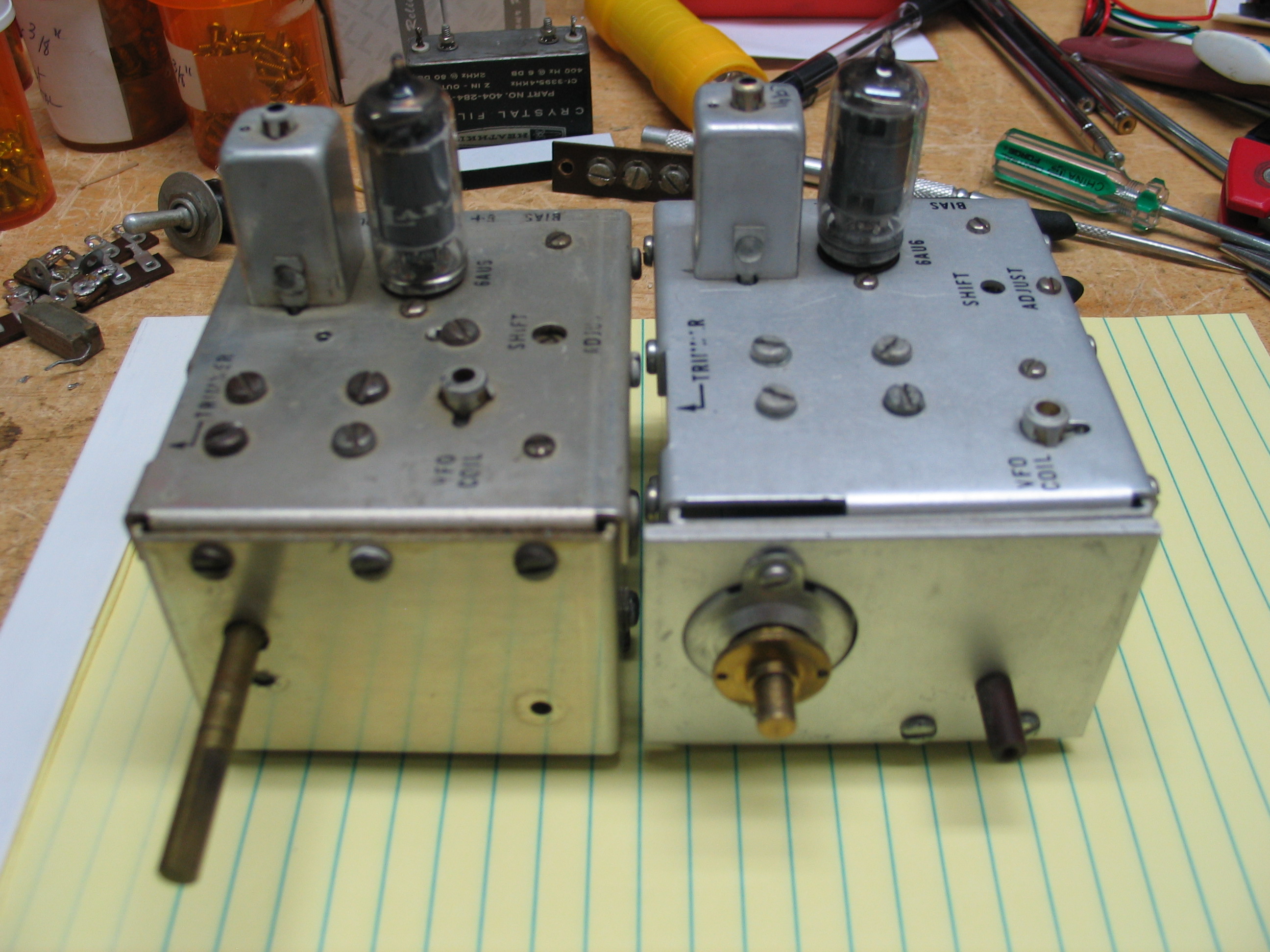
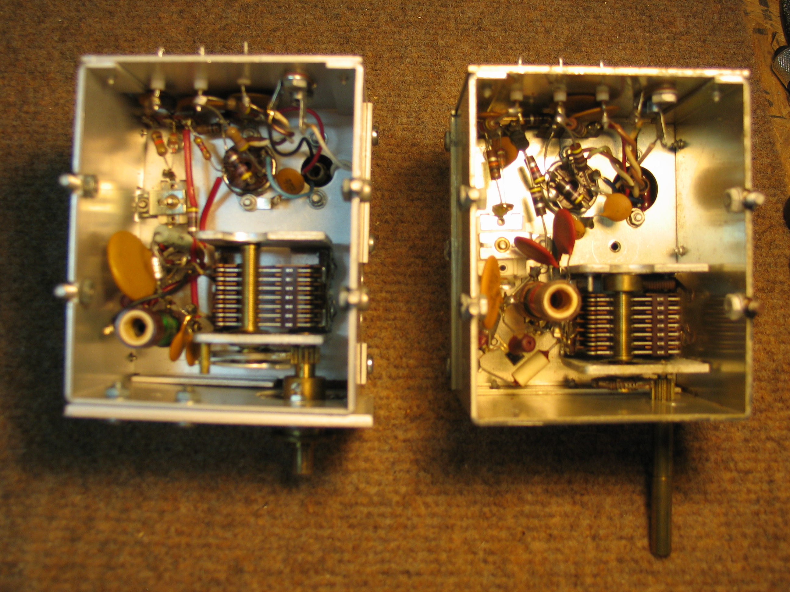
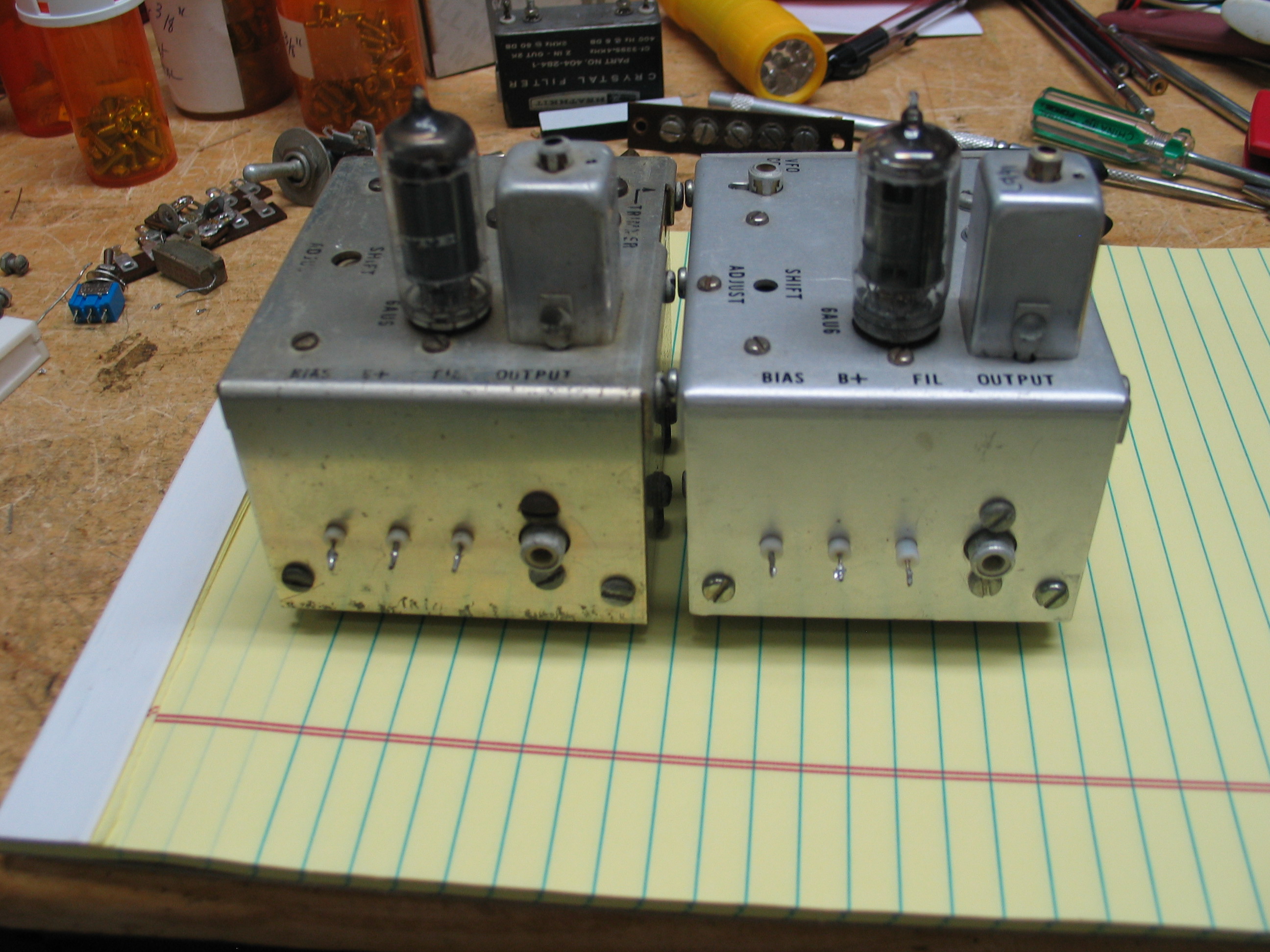
There are differences in the 2 LMOs. For example, the HW-100 LMO on the left will not work in an HW-101 nor will an HW-101 LMO on the right work in an HW-100.
The LMO tube is NOT the oscillator but rather it’s a “Buffer Amp”. The oscillator is solid-state MPF-105 FET. Both LMO frequency ranges are the same, 5.5 MHz at the bottom of ALL bands and 5.0 MHz at the top of ALL bands.
The LMO tuning ranges do not change when the band changes like some older VFOs do (HG-10, VF1, etc).
The LMOs are used in both RX and TX. A failed LMO will result in the loss of both RX and TX.
=========================================================
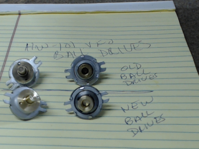
NEW HW-101 VFO Planetary Ball Drives
Cleaning variable capacitor flex shaft video (once the VFO is removed from the HW-101):
Replacing the HW-101 VFO Jackson ball drives (once the VFO is removed from the HW-101)
https://w5rkl.com/wp-content/uploads/2018/08/Replacing-Jackson-Drive-on-HW101-LMO.wmv
==========================================================
=========================================================