Heathkit DX-60B Third Edition
Full Rebuild
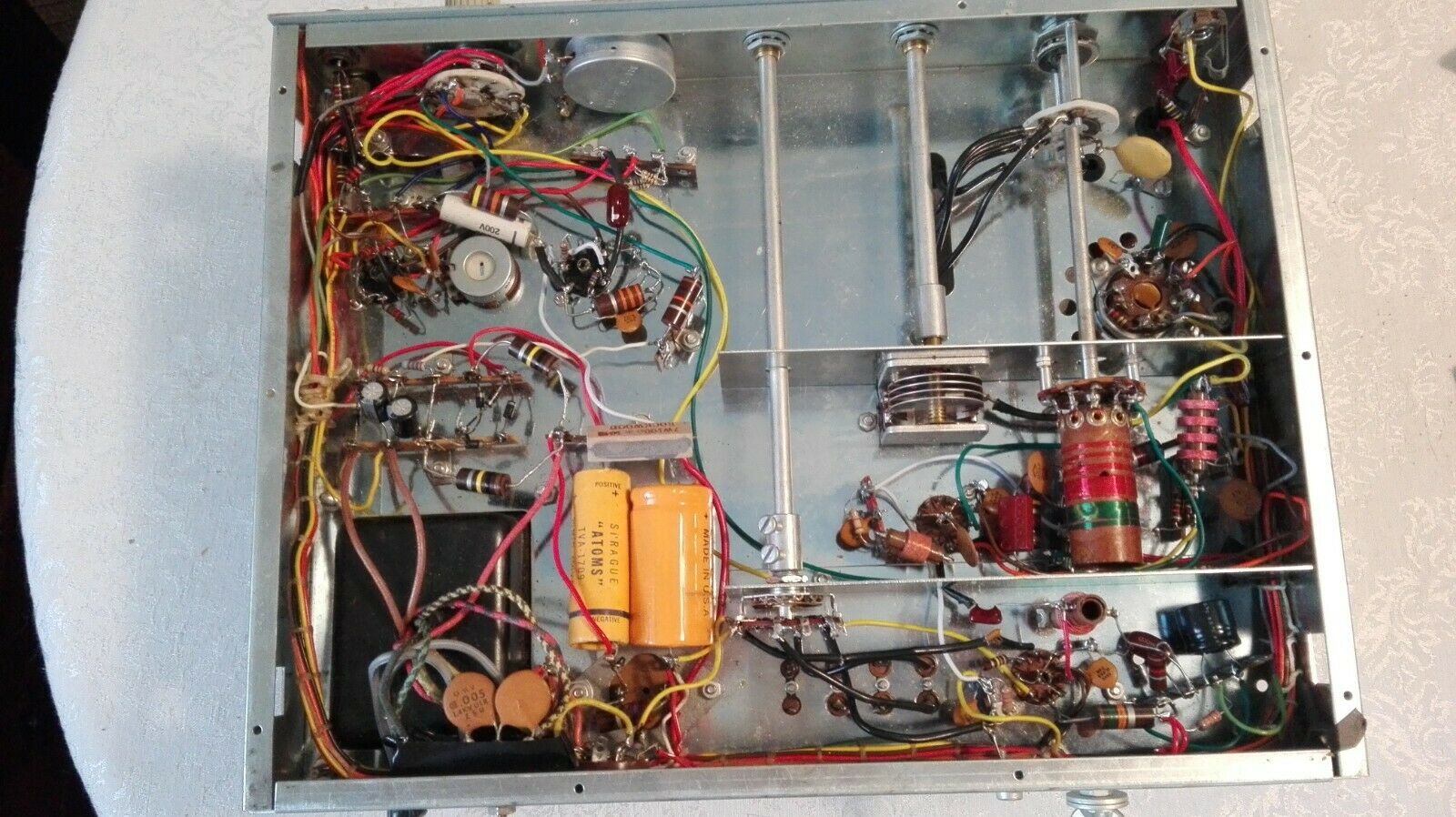
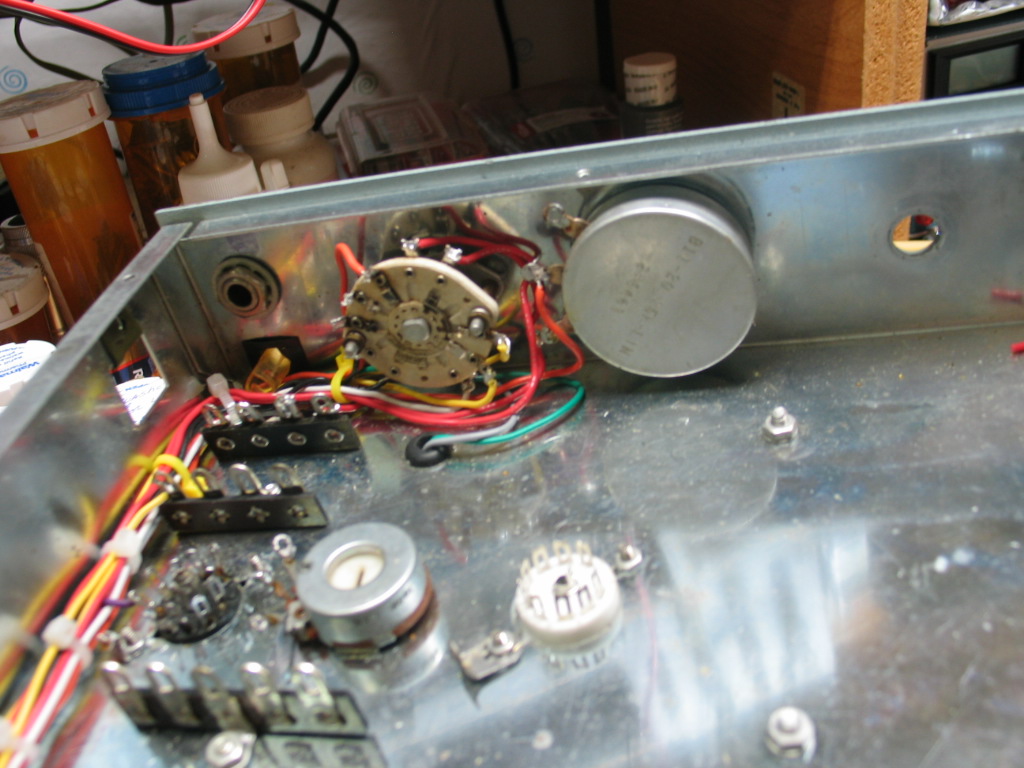
I picked this DX-60B up on eBay late Sept. The wiring harness before disassembly. Note how messy the wiring layout is.
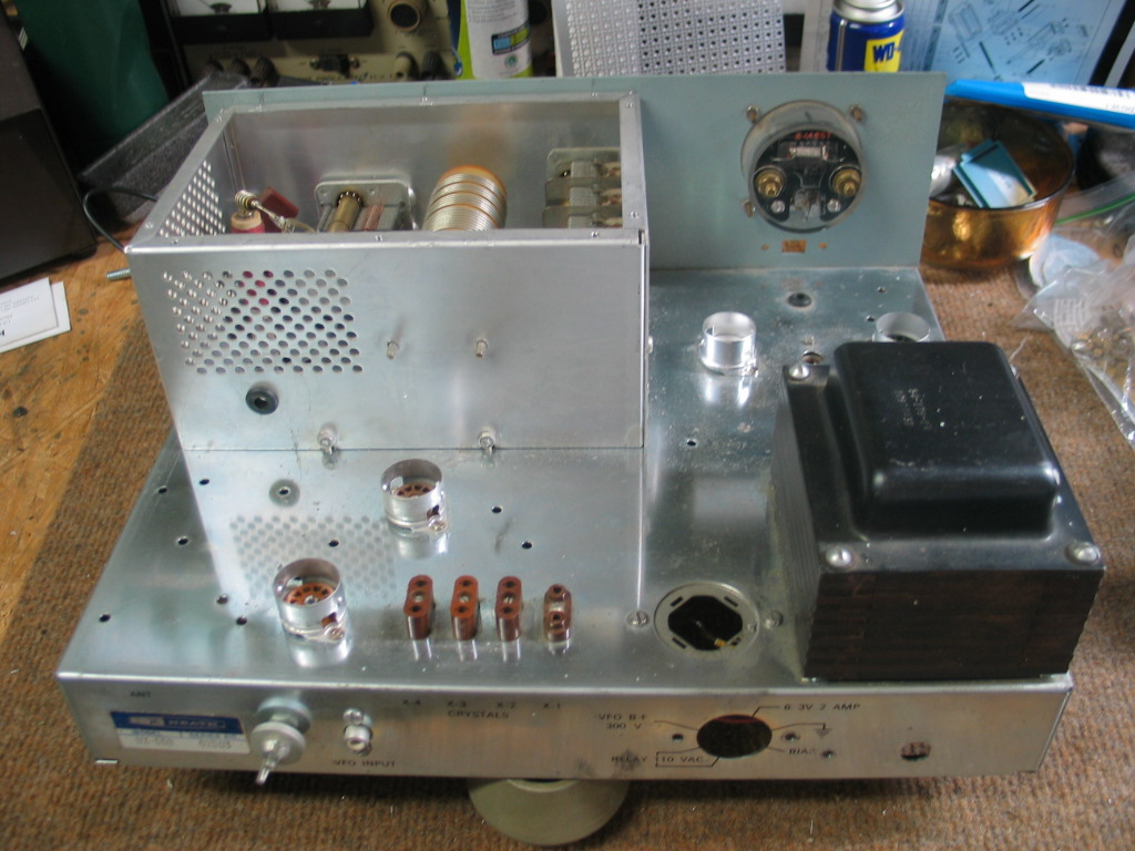
The rear view shows the missing output filter and the missing final amplifier top cover. I had to replace the 6146 tube socket and the 6DE7 Modulator tube socket, they both had broken pins. I disassembled the chassis by 95%, leaving the tube sockets, power transformer, final amplifier, and power supply filter capacitor mounting plate in place. The chassis surface is clean and shiny as the day it was removed from the “kit box” during assembly.
The wiring harness was a total disaster. The wrapping was a mess, numerous wires in the harness were missing, which made it unusable. I used a DX-60A that had a complete, non-hacked, original harness as a guide. I used the DX-60B manual Pictorial’s 2 and 3 and the schematic to map each wire end to end. After a couple of corrections in the mapping, I finalized the new wiring harness and documented it in an MS Excel Spread Sheet. The Spread Sheet was used to route each wire, one at a time, from one end to the other for a new wiring harness.
=========================================================================
The acronym “BOP” is short for “Break Out Point”.
Left side BOP’s A and B with the Driver and Oscillator shields temporarily installed for the picture and to ensure both shields fit without causing chaffing the new harness wires. 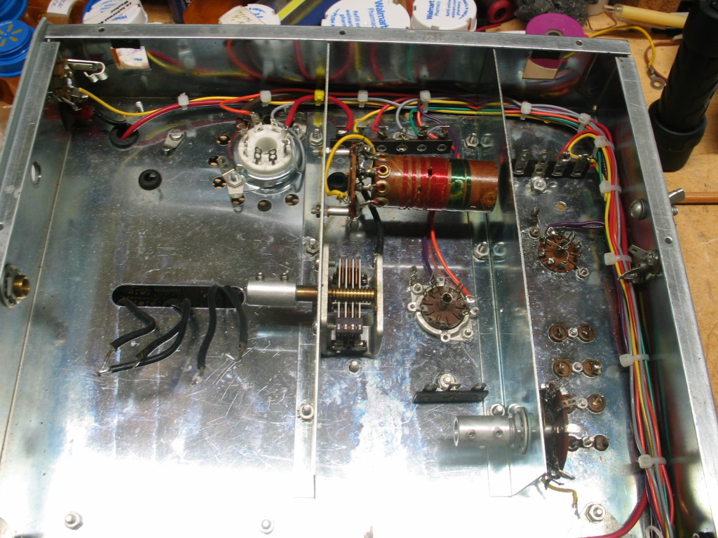
Rear view portion of the new harness. BOP’s C, D, and E (left to right) are along the rear apron. BOP “F” Terminal strip “J” is visible to the left of the transformer wires. The 7 tab terminal strip to the right of the octal socket is where the primary AC power connection is.

Right side BOP G and H. BOP “G” is just to the right of the power transformer, the transformer wires are draped over terminal strip “F” at BOP G. Note new ceramic tube socket for V4 Modulator.
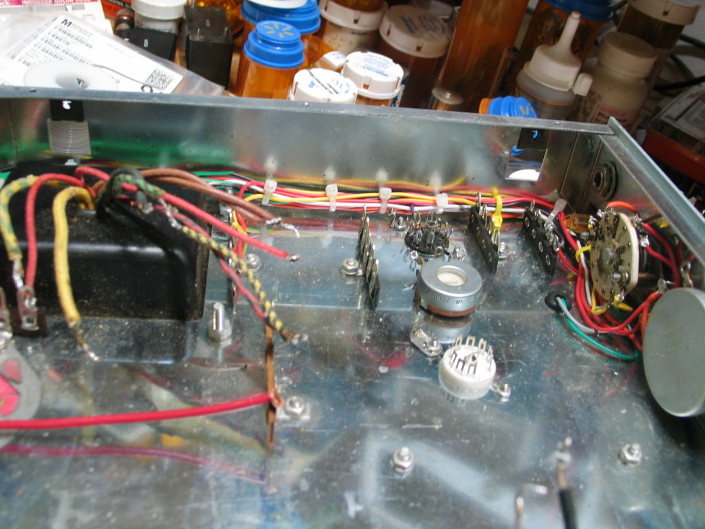
BOP “J” and “K” on the inside front apron. The corner is a bit crowded with the connections to the Function switch and DRIVE level control pot (25K 5 watt). The POWER ON neon lamp is visible directly below the MIC socket. The Gray and Green meter wires are routed through the small rubber grommet “B” to the top of the chassis.
Each BOP wire connection was fully tested with an analog ohmmeter to ensure the connections were as documented in the Spread Sheet. All wires used in the wiring harness are new 22awg solid copper wires. The DX-60B capacitor kit from Hayseedhamfest.com arrived and was installed. I purchased the complete assembly manual from w7fg.com to assemble the DX-60B. There were some steps that were already completed so those were checked then assembly continued on with the next set of steps.
===============================================================================
Rebuild Completed
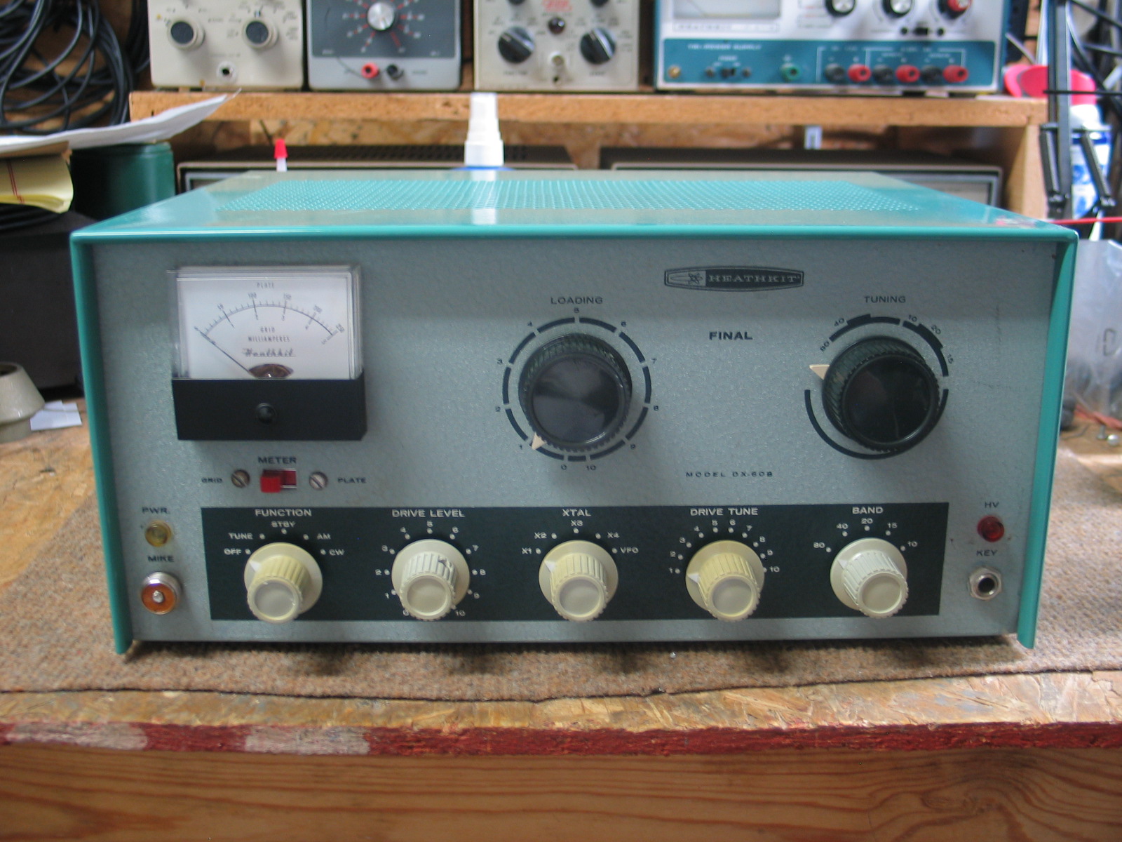
Front View: The top cover came from an HW-16 parts radio. It’s in excellent shape. I did not paint the top cover and the paint is not Heathkit color BUT it makes the DX-60B look great!!! The front panel was gently cleaned with water and Windex. There was a small vertical black mark on the right side (no longer visible) I removed it by gently rubbing it with a cotton cloth wet with DeoXit F5 Fader cleaner/lubricant.
The only 3 changes made during assembly were, I ran an entirely new wiring harness using new wires. The original wiring harness was damaged beyond repair, I replaced the 2 wire dual fused power cord with a 3 wire ground power cord and I added a single fuse holder on the inside rear apron with a 3 amp fuse.
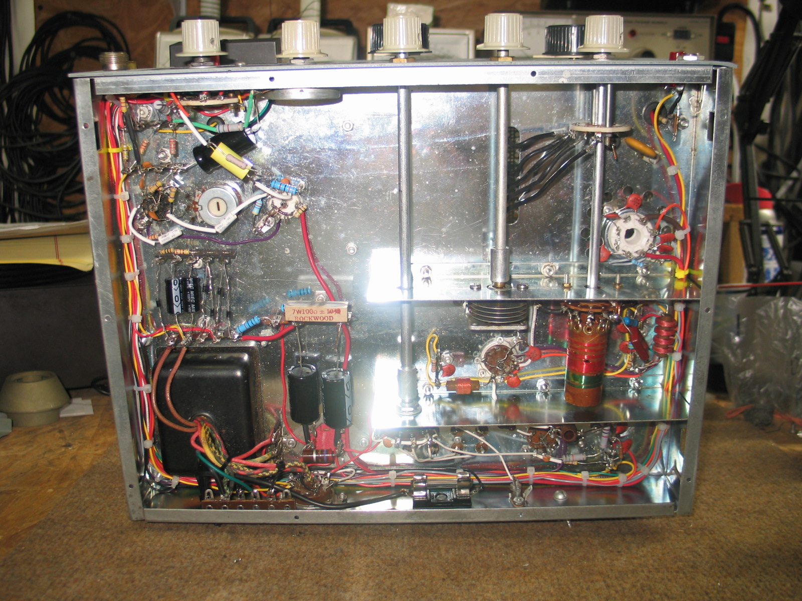
Bottom View: All new wiring. 99% of the old fixed capacitors and resistors were replaced with new capacitors and resistors. Any reused original resistor(s) were checked for tolerance rating. New diodes and electrolytic capacitors replaced the original components. All new point-to-point wiring and most of the multi-tab terminal strips were replaced with new terminal strips. New mounting hardware replaced the old discolored hardware. There were 2 problems experienced during initial testing. The first problem was a bad solder connection to driver tube V4’s center terminal ground which resulted in the loss of RF from the driver stage V2 to the final amplifier V3. The second problem was the loss of key-down GRID meter indication in TUNE. The first problem was fixed by reheating and applying additional solder to the driver tube socket center ground post. The second problem was fixed by moving one lead of the 1.1mh RF Choke at BOP “B” terminal strip “N” from tab “6” to tab “5”. The main AC power cable wiring was changed in order to use a single fuse holder mounted on the inside rear apron. This also changed the wiring to the octal socket’s 120VAC pins 5 and 6 provided 120VAC for a T/R relay.
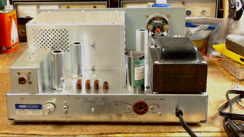
Rear view: I found a couple of output filters on eBay. One had the RCA socket and the other had the SO-239 socket. I chose the output filter with the SO-239 socket since most of my coax jumpers have PL-239 plugs. I cut a replacement cover for the top of the final amplifier enclosure out of perforated aluminum and mounted it with new #6×1/4″ sheet metal screws.
Final testing setup with DX-60B and HG-10 VFO feeding into an MFJ-260C 50-ohm dummy load and a Heathkit HM-102 2KW watt meter produced 50 watts out on 80 thru 15 and 30 watts out on 10. This DX-60B operates like a “brand new” DX-60B that has never been put on the air!!! That “never been on the air” will soon change.
=========================================================================