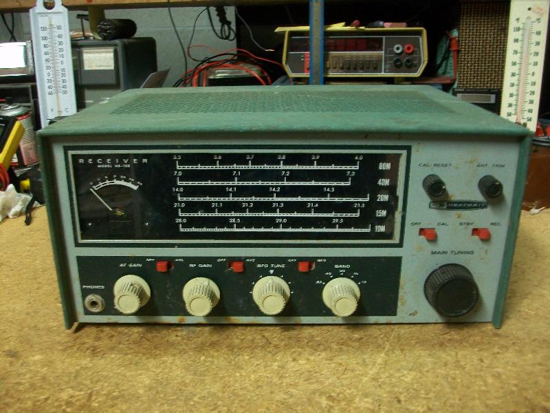
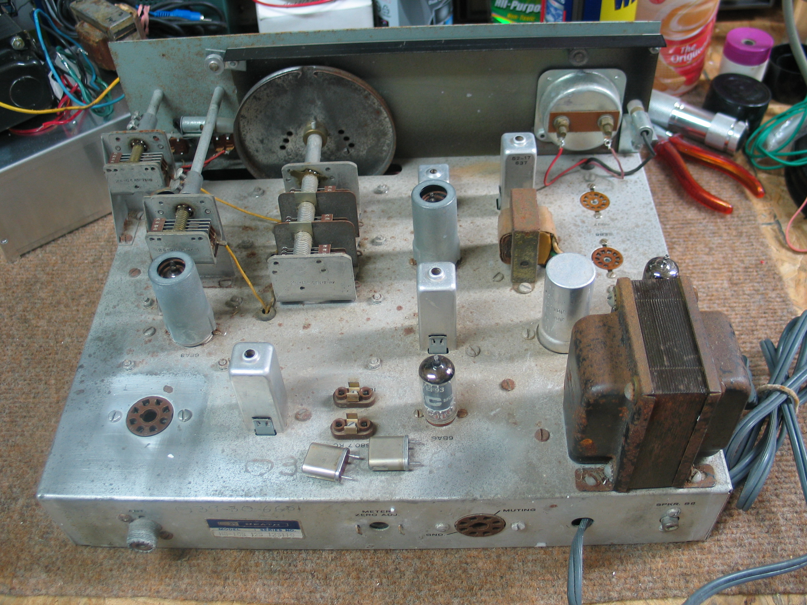
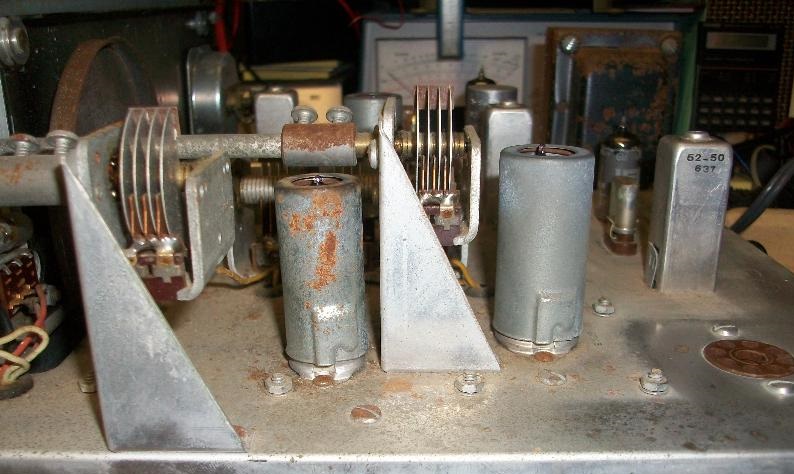
Before:
The front panel has rust pit and paint damage due to rust. The power transformer has rust as does the top of the chassis. The point to point wiring is old and dried up. The power cord is a 2 blade non-polarized plug. The triple capacitor can is old and is an accident waiting to happen. What’s not shown is a previous owner scribe his name, address, and SSN on the chassis in 2 places, something that was done many years ago for identification in case of theft. That information will be removed. The top cover, not show, has rust pits and aging paint discoloration. The DET/ANL/AGC and audio tubes are missing as was the optional Heathkit HRA-10-1 100Khz calibrator. The RED dial pointer was also missing. Both sides of the bottom cover has a lot of rust. A good thing is that all 7 knobs were dirty but all were in excellent physical condition. Finding the original knobs can be rather difficult, especially in good, not cracked, physical condition. The dial glass was dirty but also in very good physical condition, no cracks or scraps and the White characters and lines were solid, not faded.
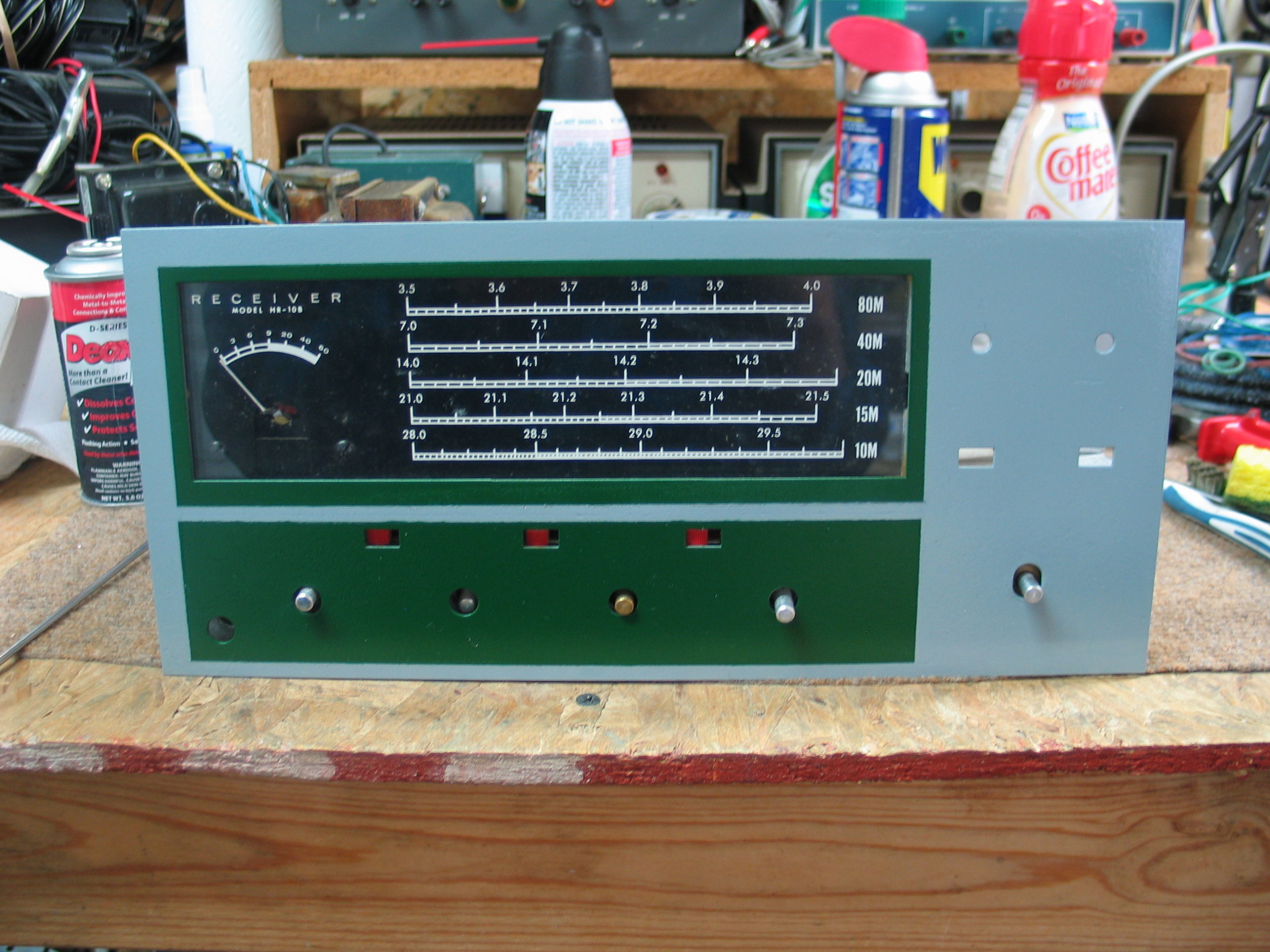
Front panel BEFORE attempts to repair/repaint. Simple cleaning caused the paint to begin rubbing off. The cleaner was Windex. I measured the areas from the sides, top and bottoms and inside the dial opening so I could recreate the green color (see next picture).
Before:
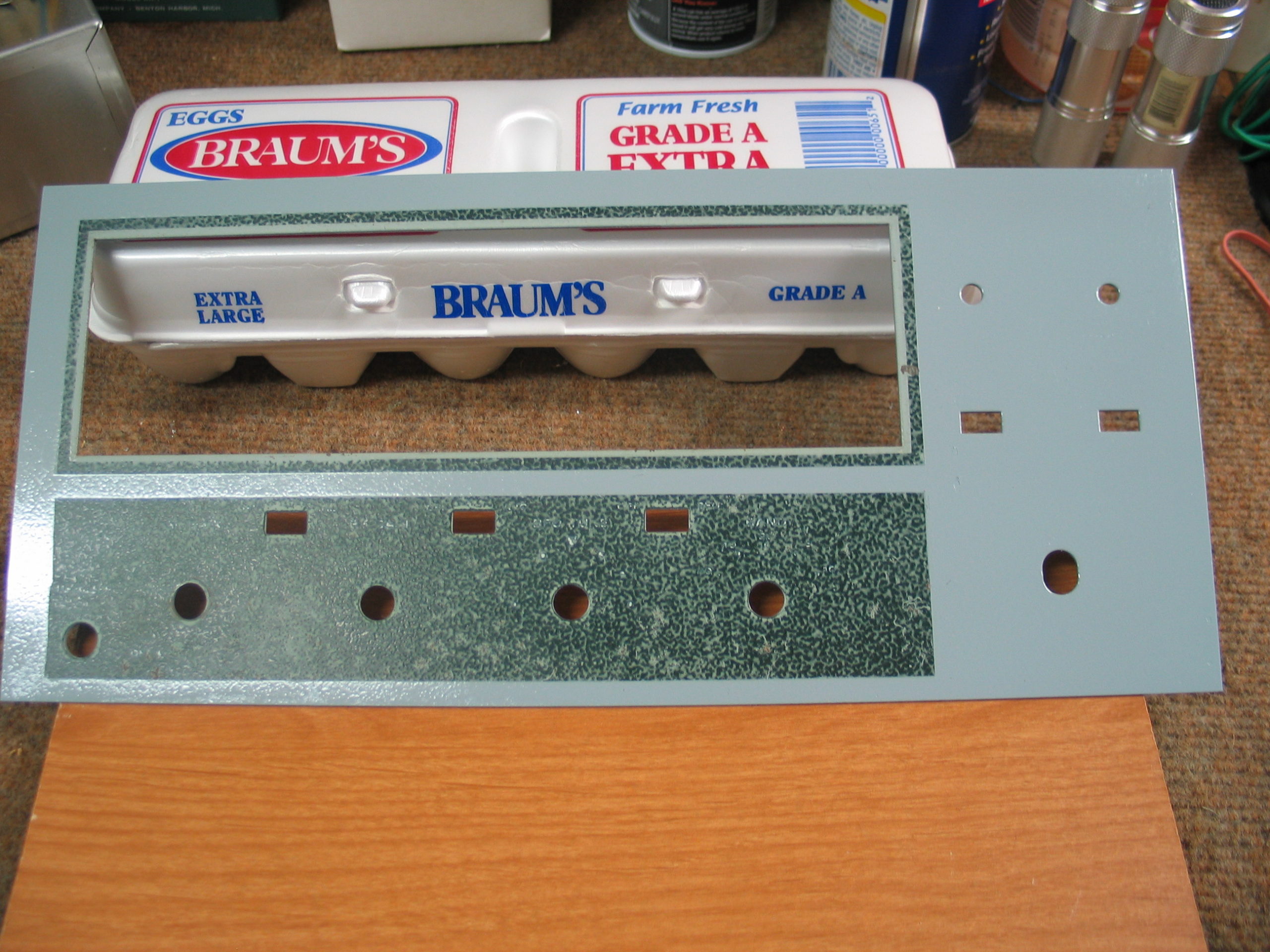
I stripped the original panel, using CitrisStrip paint remover. I then sanded the panel and thoroughly cleaned it and allowed it to dry. I applied a coat of Rustoleum gray primer. Using the measurements I masked off the areas where the dark green is to be applied. I applied a coat of winter’s gray. After it thoroughly dried, about 2 to 3 days, I masked off the gray areas leaving the areas where the dark green is to be applied. It’s not Heathkit green but it looks 100% better than the panel originally did.
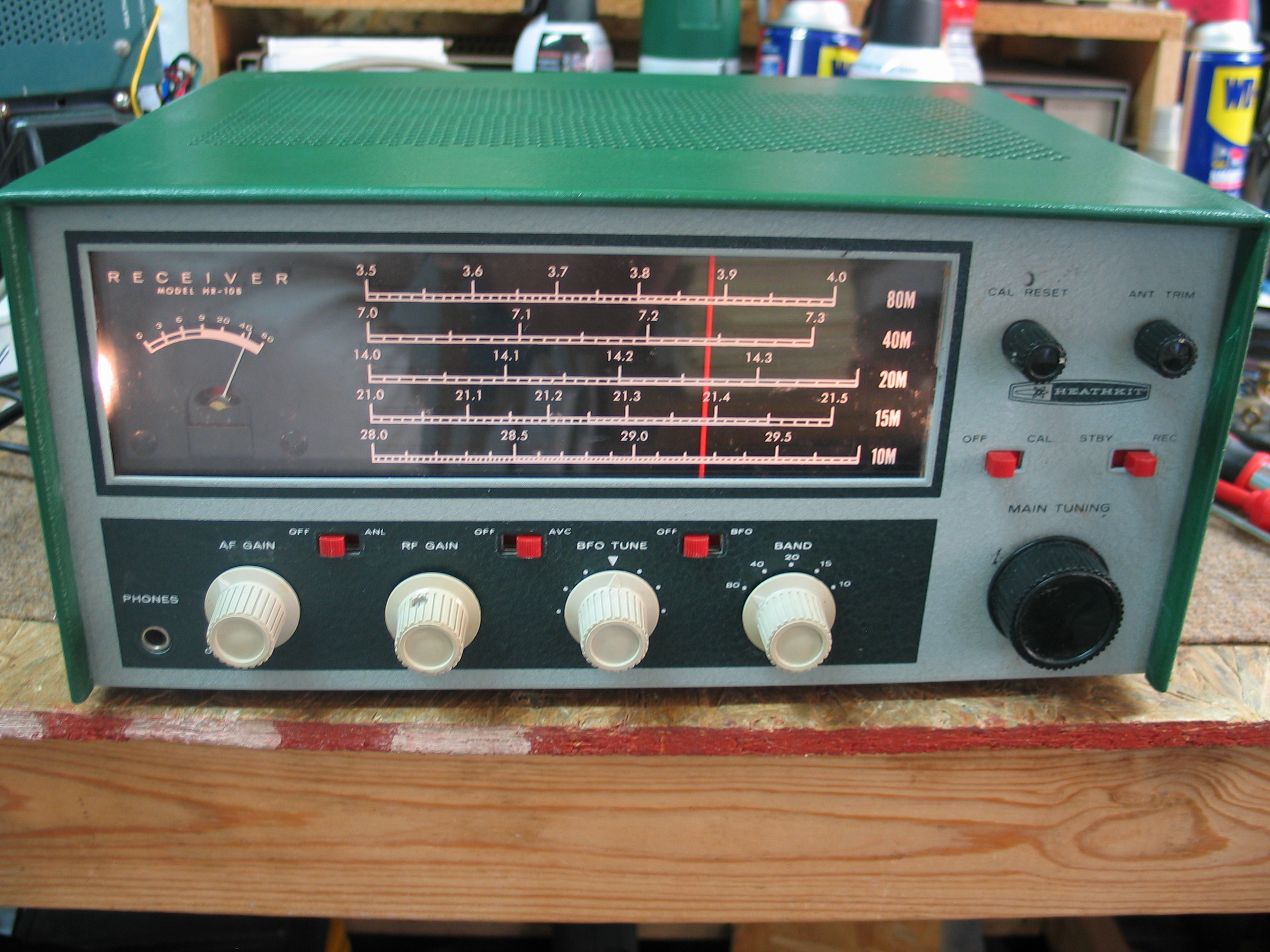
Final painting with new decals on the right side. I looked for ways to make White decals for the controls in the dark green area. So far I have not had any luck. Until I can figure out how to make White decals for the controls, I found and used another very good condition front panel (see pictures below). I still have this incompleted front panel, I just have to figure out how to make some white decals for the controls and slide switches.
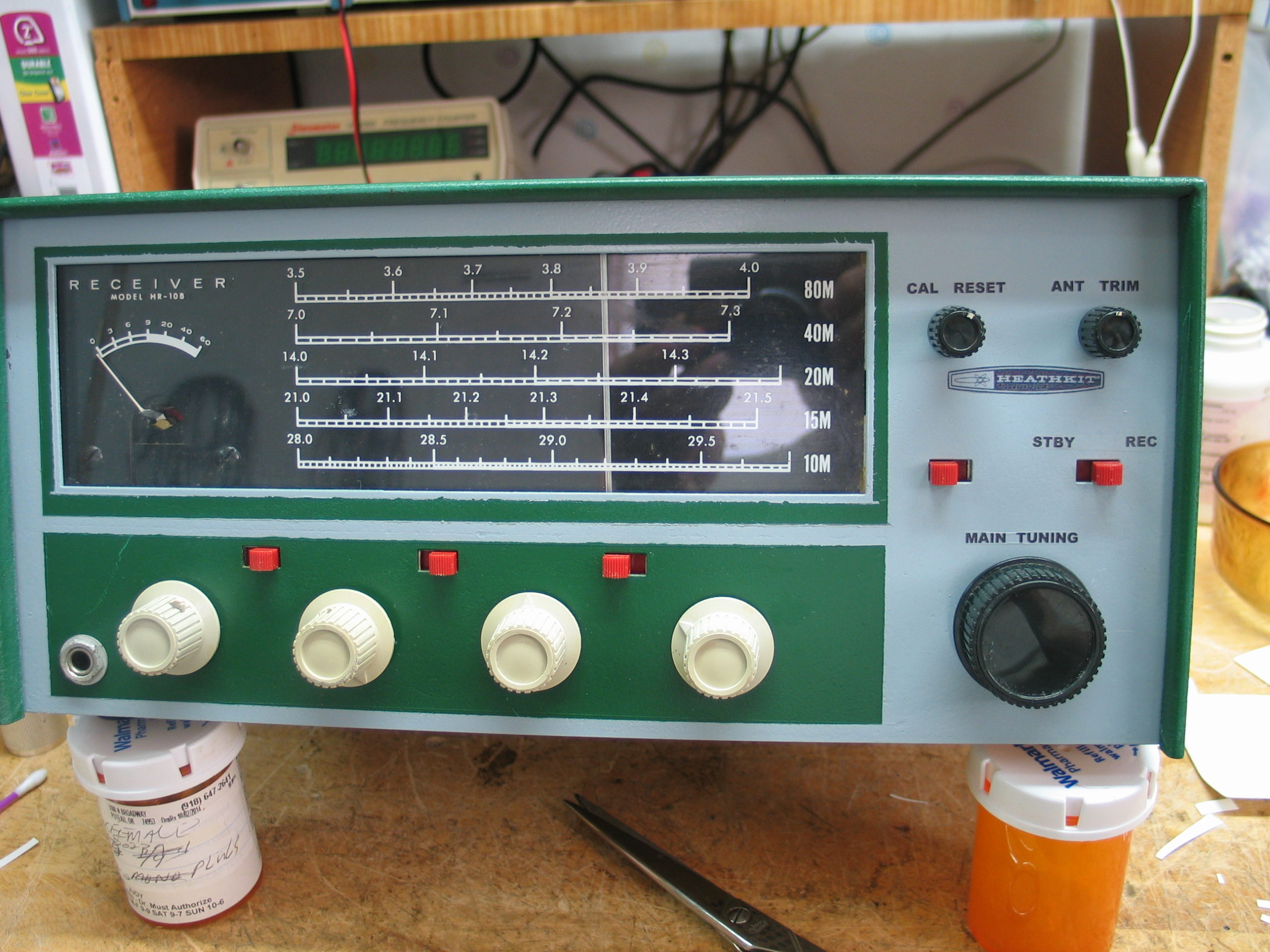
After:
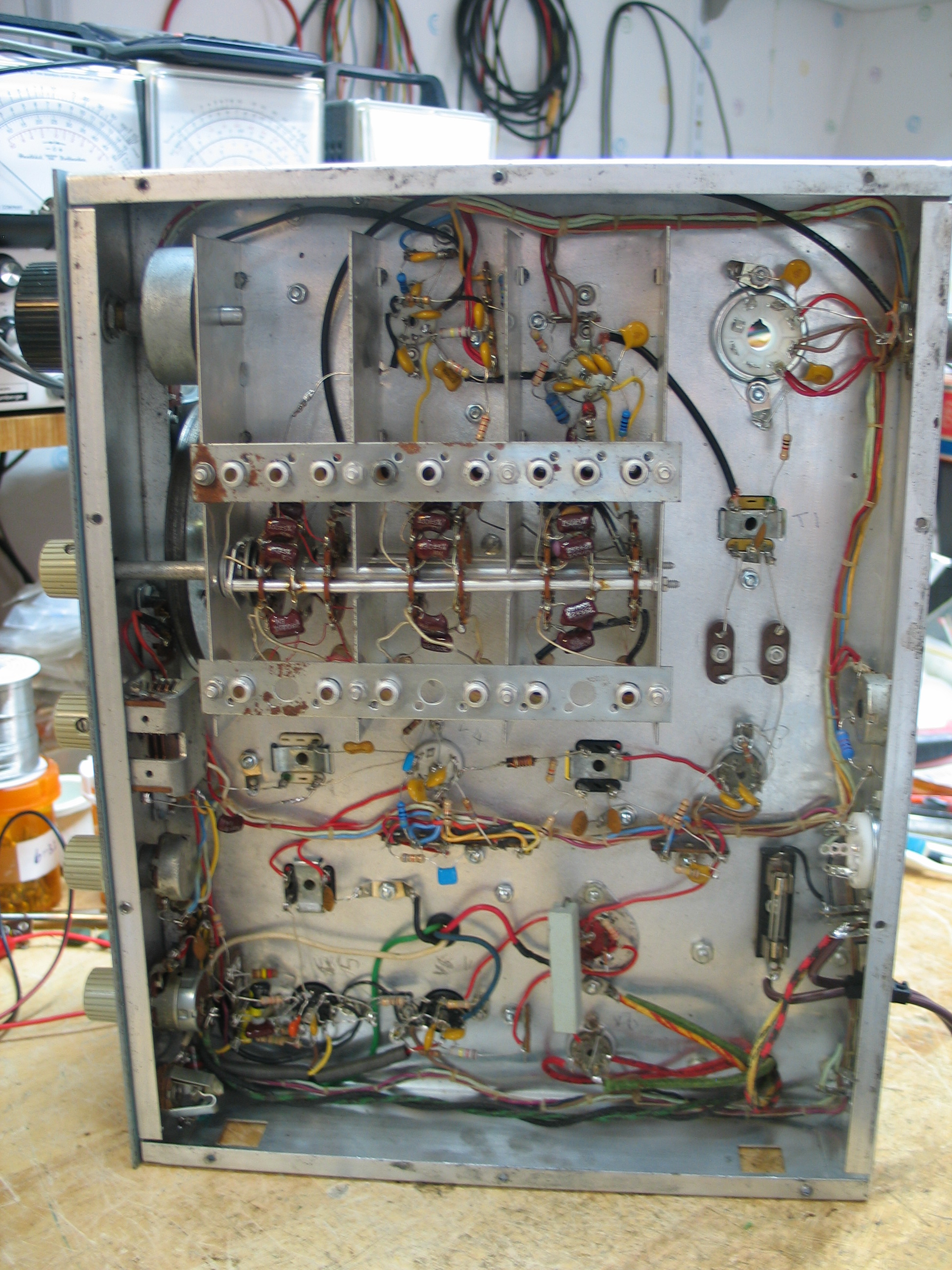
A full restoration of an HR-10B receiver is not simply replacing a few out of tolerance resistors, capacitors, and electrolytic capacitors. A full restoration of the HR-10B receiver is to fully disassembled the receiver down to a bare chassis then perform the following steps.
All fixed resistors and capacitors are replaced with new components
All electrolytic capacitors, including multi-capacitor cans, are replaced with new capacitors
All point to point wiring is replaced with new wiring
Wiring harness is carefully disconnected, removed, cleaned, and the break out ends are stripped of insulation for reuse
All potentiometers, slide and rotary switches were thoroughly cleaned, inspected for proper operation. Switch bearing assemblies were cleaned and lubricated for ease of operation.
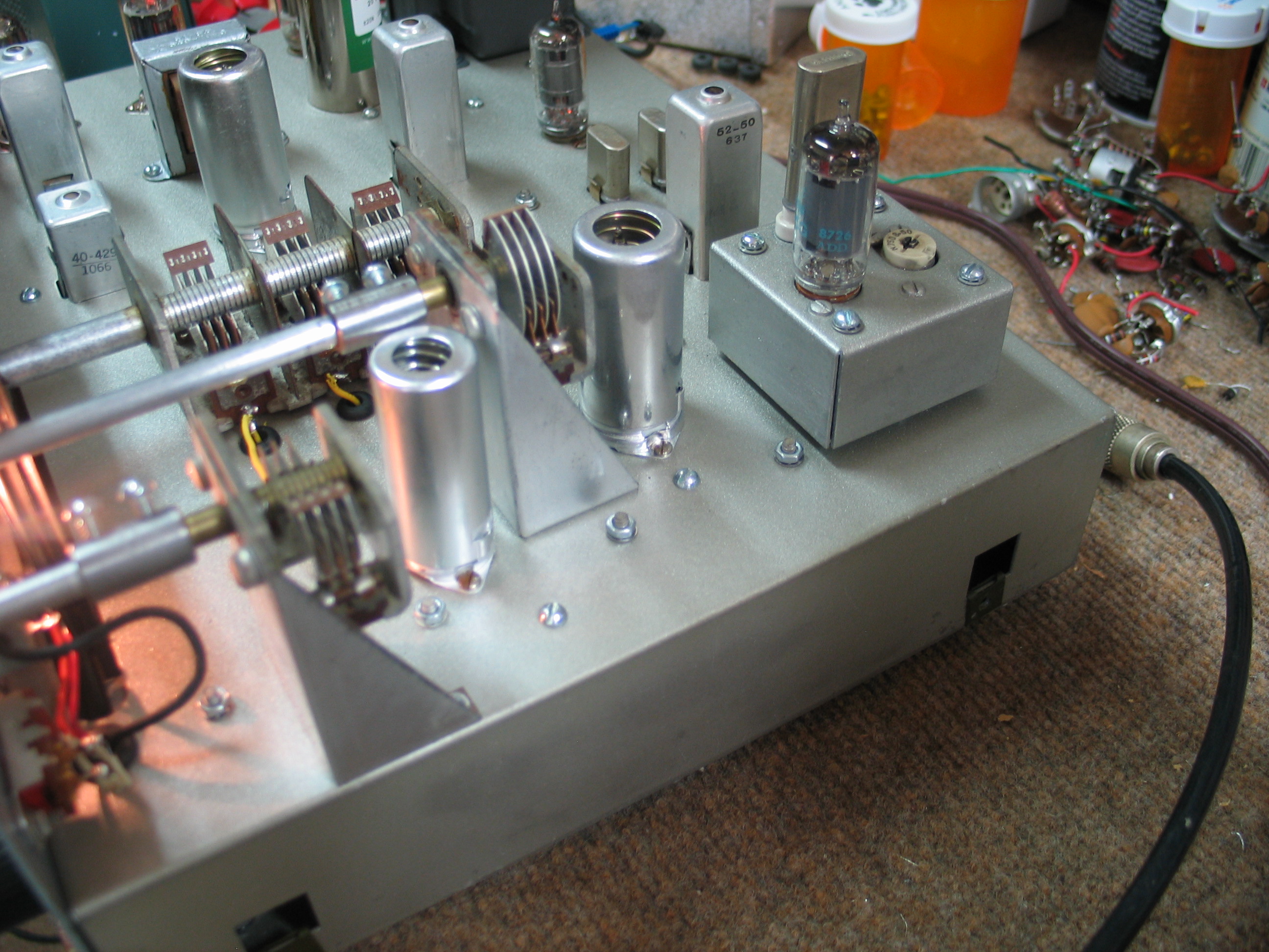
All variable capacitors were thoroughly cleaned, inspected for bent plates, corrosion pits, then the ball bearing end, if so equipped, is lubricated with DeoXit L260ap grease. The flexible shaft to frame connection is cleaned with DeoXit D5 to remove any dust/dirt collected at that point
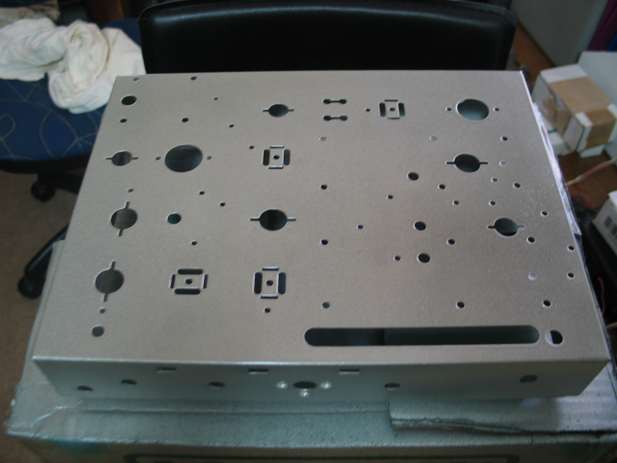
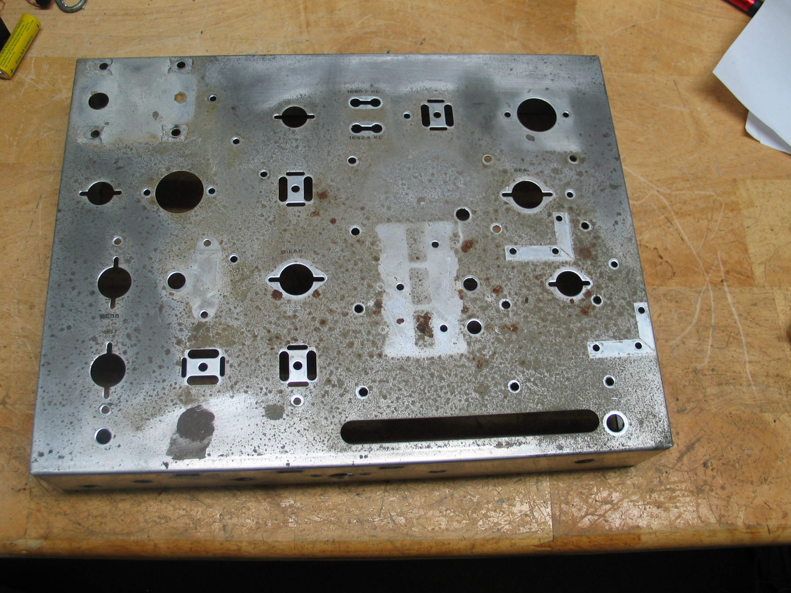
The chassis and support brackets were sanded to remove any rust and corrosion then painted with Rustolium Metallic Nickel paint from Walmart
Each shaft coupler is cleaned of all rust and corrosion using steel wool and a 1/4″ drill. Wrong or damaged set screws are replaced with new machine screws
Most, if not all mounting hardware was replaced with new 6x32x1/4, 6x32x3/8, 6x32x1/2 machine screws, #6 internal star washers, and 6x32x1/4 machine nuts. The top cover and bottom cover plate mounting screws are replaced with new 6×1/4 sheet metal screws.
New ground tabs and multi-tab terminal strips replace old worn out terminal strips
Meter is checked for proper operation by using Ohms Law to calculate the value of series resistor(s) and a 6 volt battery for a Full Scale (FS) meter movement. Meter should move freely from zero to FS without hang up.
The receiver is reassembled using the full assembly manual.
I don’t rely solely on the resistor color bands and/or the resistor’s value printed on the packing the resistor came in, I check each resistor with an Ohm Meter.
A new 2 blade polarized power cord replaces the original 2 blade non-polarized power cord. If there is no fuse holder, I install a fuse holder and calculate the proper fuse rating using Ohms Law formula “PriCurrent = Pwr in watts / AC line voltage x 1.5”
Once reassembly is complete and before any power is applied, a thorough inspection of all connections and component placement to find and fix any wiring errors. Failure to do this step can lead to damage. Wiring errors and shorts found are fixed and rechecked.
Voltage measurements with all tubes removed are conducted.
Voltage measurements with Rectifier Tube 6X4 installed are conducted
Full power up test for RF Amp, local oscillator, mixer and IF strip and audio amplifier test are conducted.
An alignment is conducted and any failures found are fixed.
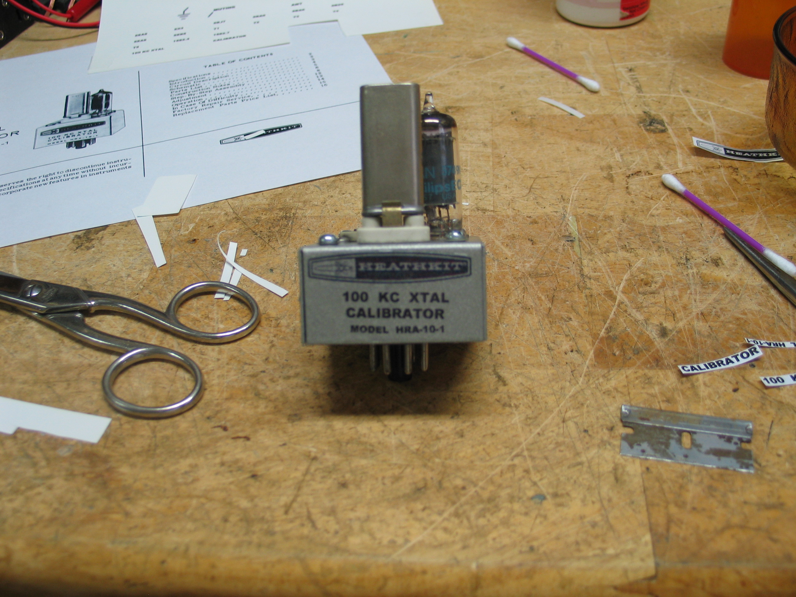
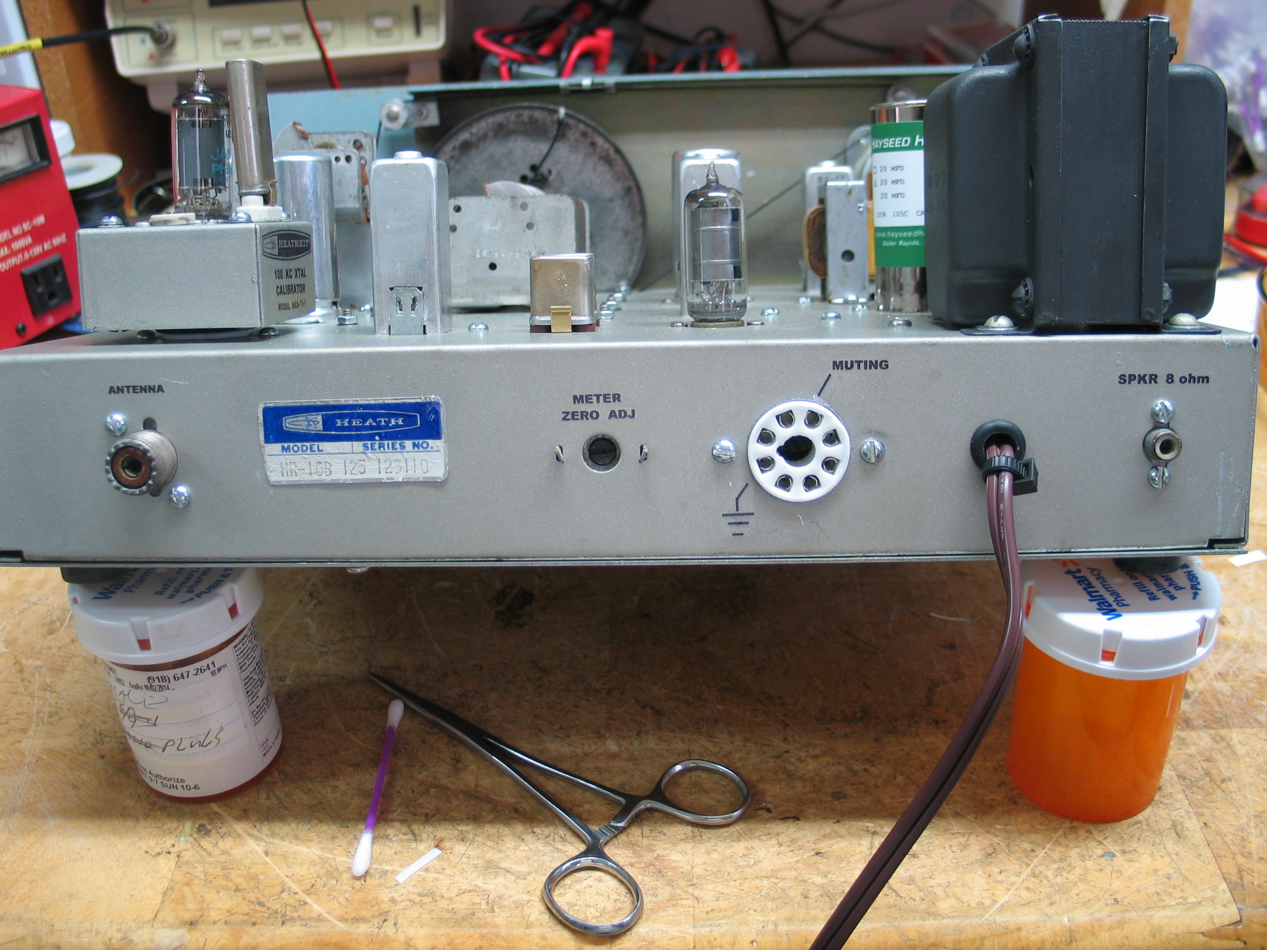
The HRA-10-1 100Khz calibrator was not included so I found one on eBay, checked for component and wiring failures, then tested for proper operation.
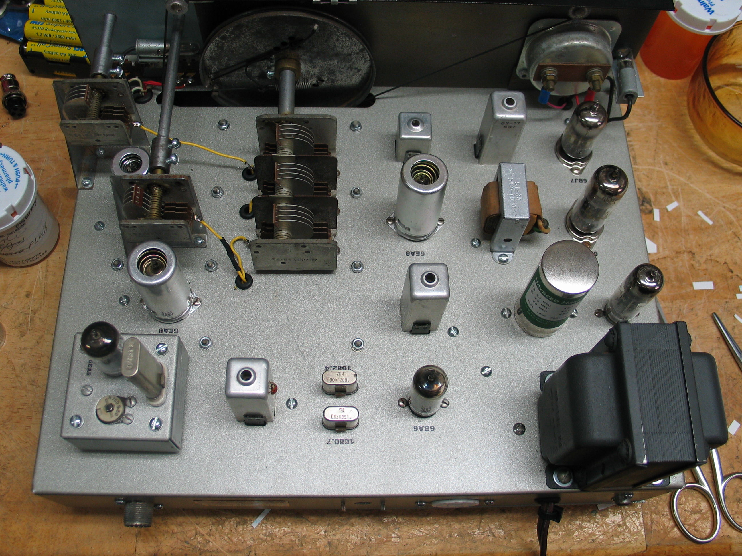
Home made decals for the rear panel and tube identification on top of the chassis were made using MS WORD and Testors Clear Ink Jet printer decal paper.
Performing a full restoration is not an easy task. The receiver should be complete before any full restoration is attempted. All new components such as resistors, capacitors, mounting hardware, dial cord if required, new power cord, new rubber grommets, new tube sockets, and new wiring should be obtained before any full restoration is started. The power transformer should be thoroughly checked for shorts and opens in the winding’s and to the iron core. Proper tools such as a solder station, small flat and Phillips screw drivers, wire cutters, medical Forceps, wire strippers, nut drivers, and a well lighted work area. A “complete” full assembly manual is a must. Take your time, don’t rush the restoration. The HR-10B, like many HR-10B found at a hamfest and on eBay, do not have the HRA-10-1 100Khz calibrator. I found one on eBay and restored it to like new condition. The original decals on the top of the chassis and rear/side apron were replaced with new decals made using MS Word and clear Ink Jet decal paper.