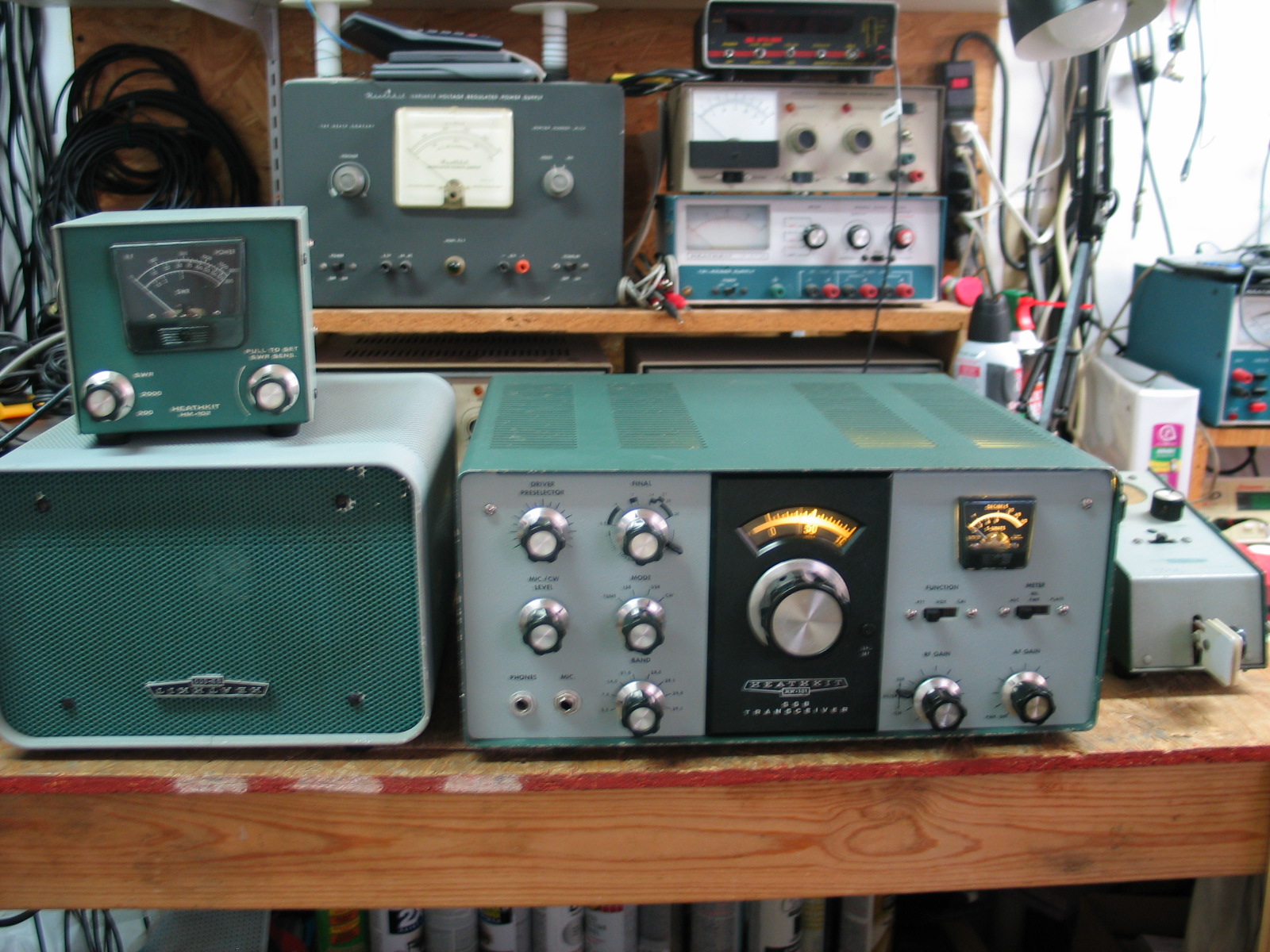
The following pictures shows my recently completely rebuilt Heathkit HW-101.
This transceiver restoration project was not an operating HW-101 transceiver that I replaced a few out of tolerance resistors, a few electrolytic capacitors, and cleaning a few pots nor was it a working HW-101 that I fully disassembled then reassembled with new parts.
I started this project in July of 2018. It took me 3 months of constant searching on eBay, various ham group members, and on-air contacts to locate and purchase all of the parts necessary to build an HW-101.
All the parts that were unique to the HW-101 such as the front panel, chassis, LMO dial with mounting hardware and clutch, Aluminum mounting and support brackets were disassembled and cleaned then thoroughly inspected. I had a spare HW-101 LMO. The LMO’s variable capacitor bearings and flexible ends were thoroughly cleaned and the bearing’s greased using DeoXit L260ap conductive grease. The top and all 4 sides of the LMO were cleaned and the Filament, B+, and Bias pins were straightened and secured in place on the rear panel. The LMO was tested using a Heathkit IP-17 HV regulated power supply, an Opto 8000 frequency counter, and a scope to ensure the LMO output was stable throughout the LMO’s tuning range.
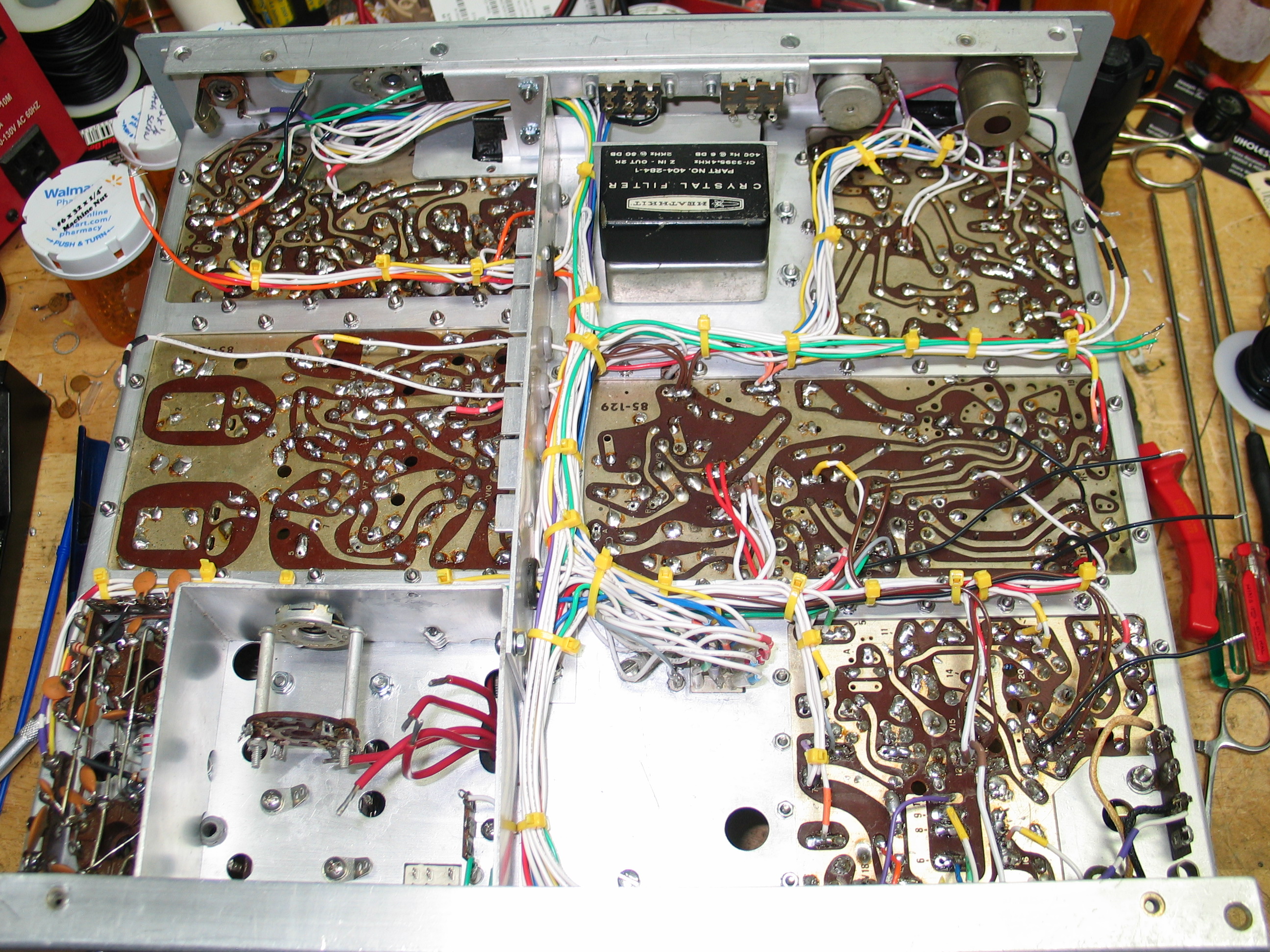
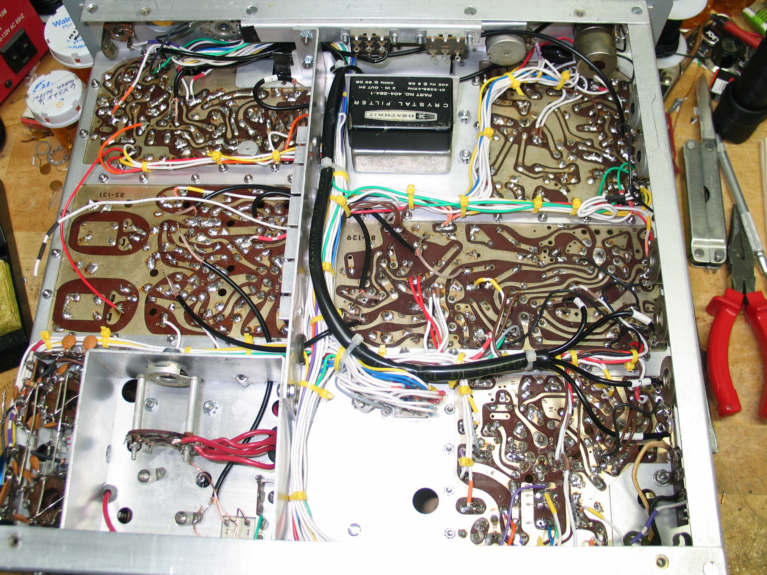
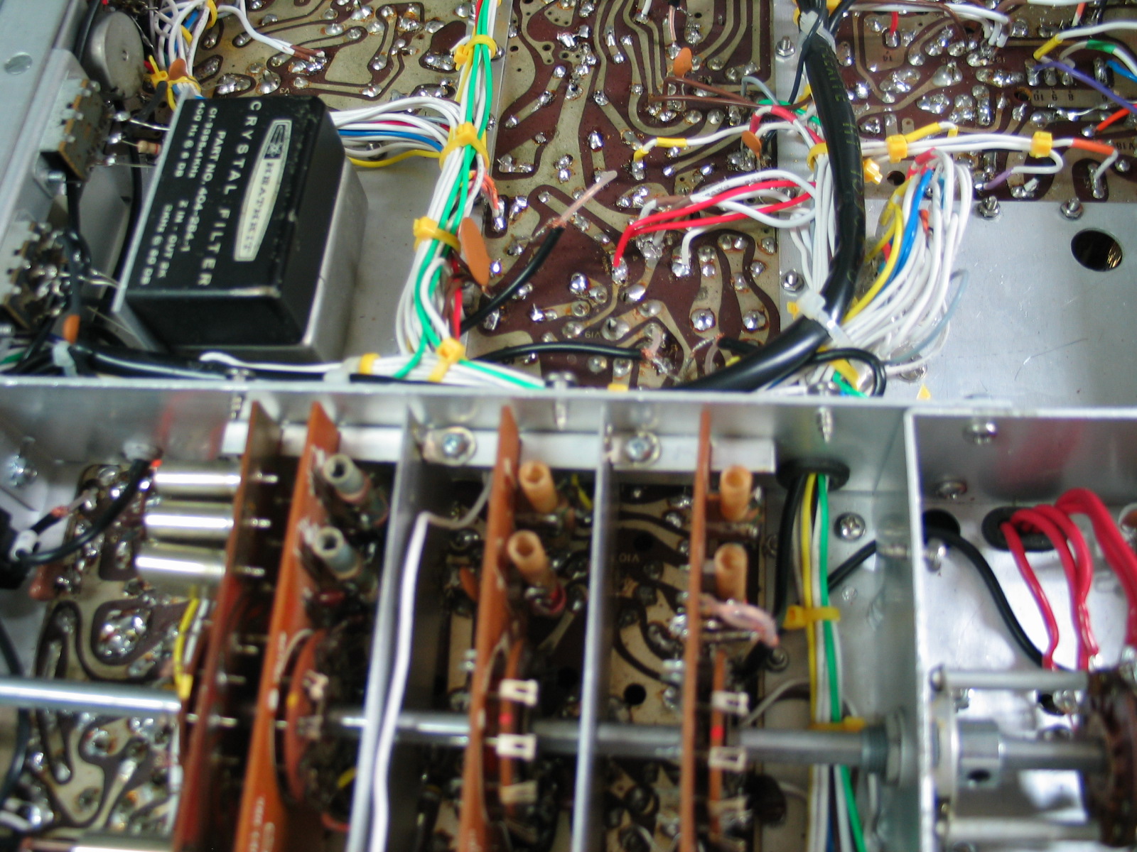
The spare chassis I had was from an HW-100 which would not work, the HW-101 chassis has a half-moon cut out on the front of the chassis to allow the dial to rotate. The HW-100 chassis does not have this half-moon cut out. Therefore, I had to locate an HW-101 parts chassis. There are not many HW-101 parts chassis’s. I found one on eBay. It had the front panel but the panel was damaged beyond repair, the color was significantly faded and the control labels were beyond use. I removed the front panel, old relays, all the boards, wiring, support brackets, etc., to a bare chassis. I reused the DRIVER PC board since the board I had, the silk screening was all but gone. This DRIVER board was in very good condition with clear silk screening but it was quite dirty. I also needed a complete, undamaged, wiring harness which this chassis had. Try finding an undamaged wiring harness from an HW-101, you won’t find one. Most eBay sellers who part out HW-101 transceivers cut the wiring harness wires then throw the harness in the trash. The area in the wiring harness that’s very important is the area around Break Out point “10”, the control relay. Quite often the harness wiring at this port is heavily damaged beyond repair. This parts chassis had a very good, undamaged, wiring harness. I needed it so I could map each wire in the harness and document the mapping in a MS Excel Spreed Sheet so I could make an entirely “new homemade” wiring harness (see pictures below).
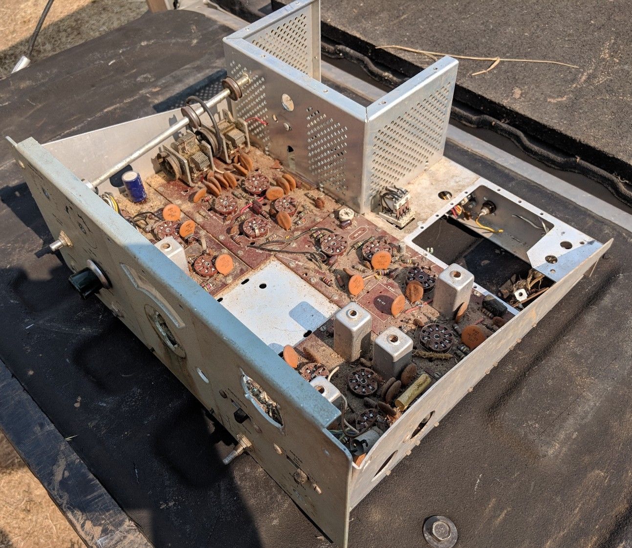
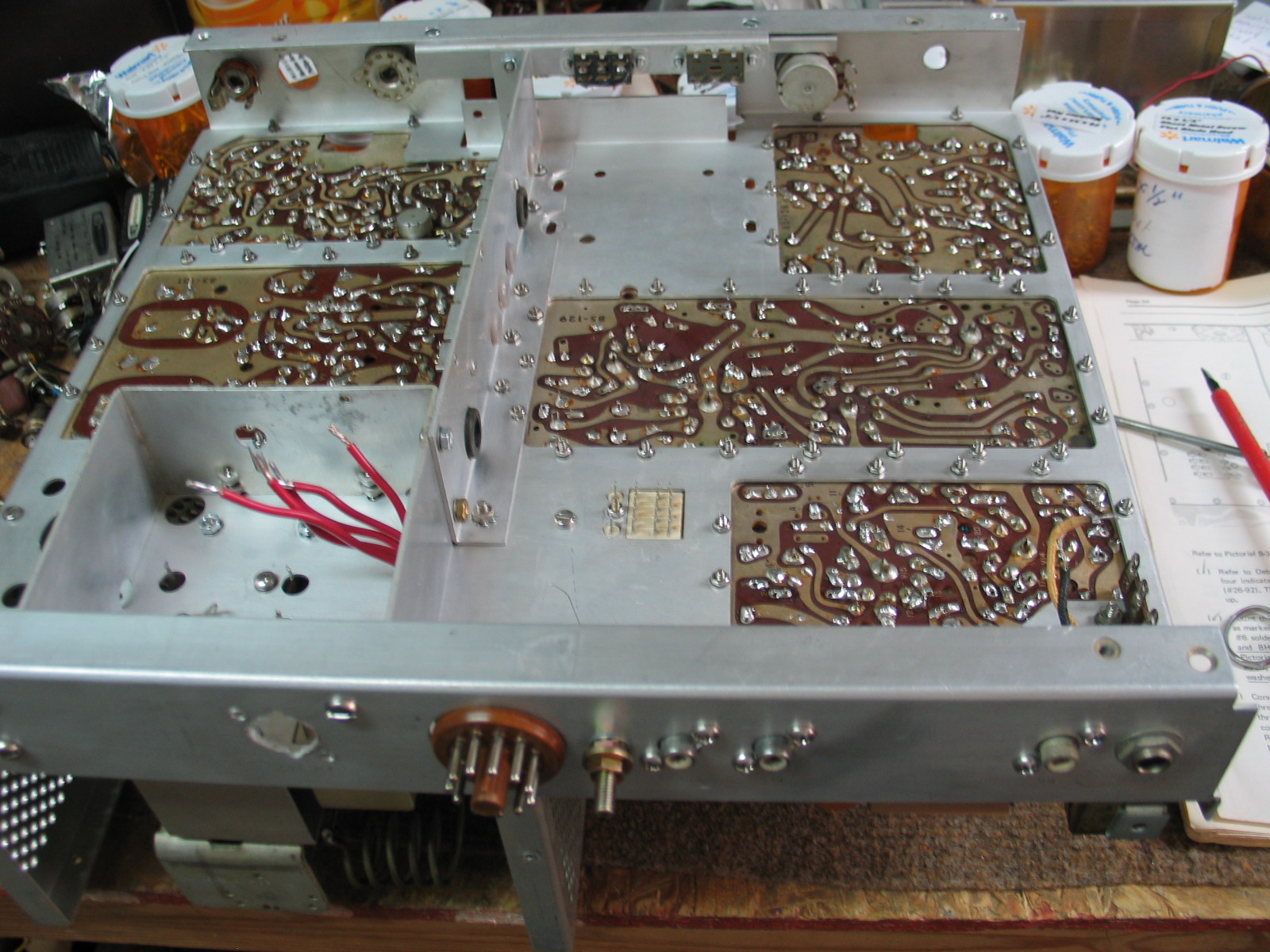
This is what the chassis looked like after completely disassembling/removing all the PC boards and other components/wiring. This chassis came from an HW-101 parts radio. Note the discoloration due to years of environmental abuse. Cleaners simply did not remove the discoloration but using a vibrating sander did. I followed the sanding, using steel wool to rub down both top and bottom and all 4 sides. This chassis restoration process required a lot of work, something that can’t be done in an hour. This process made the chassis look like new (see next picture) again.
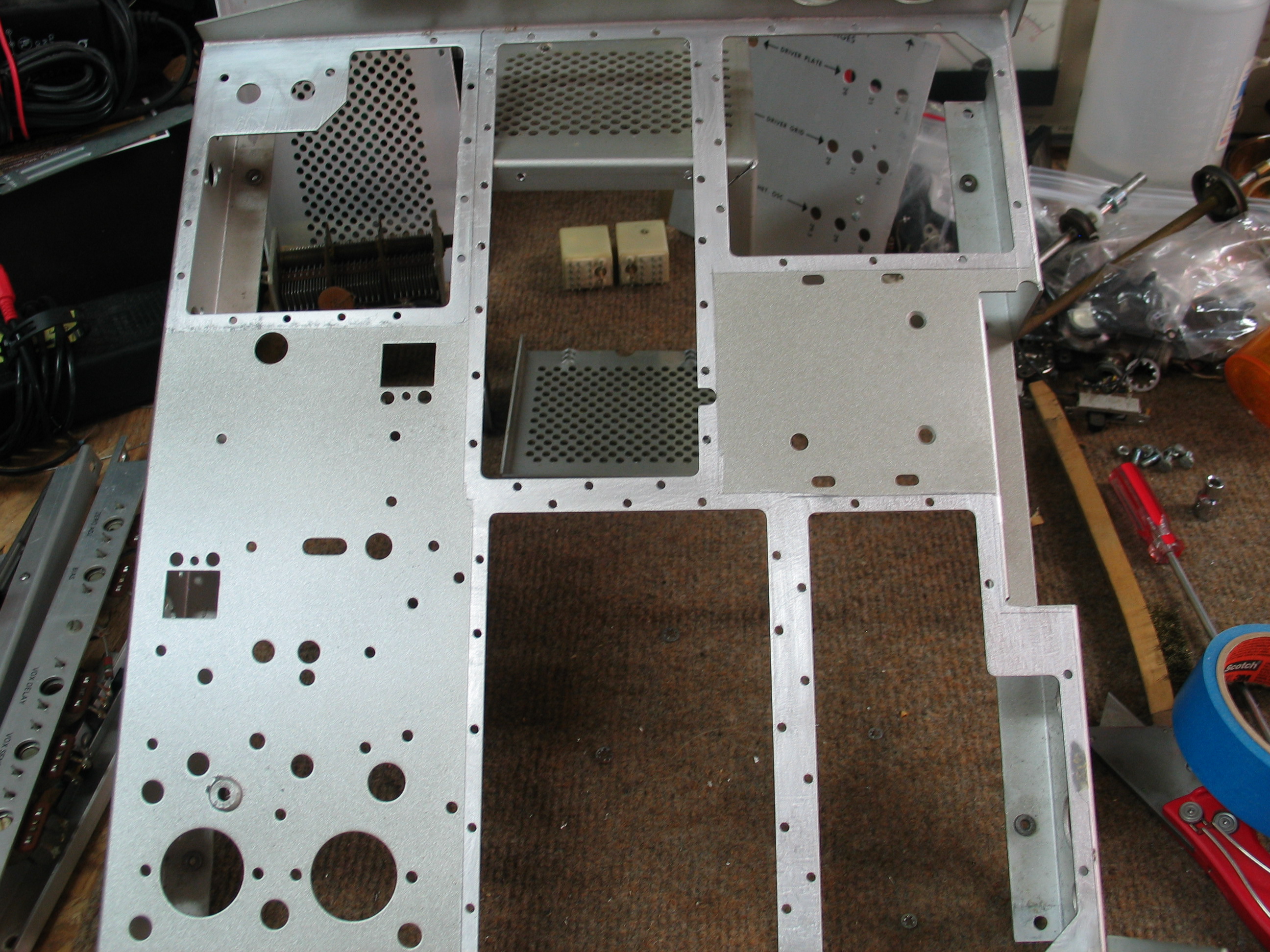
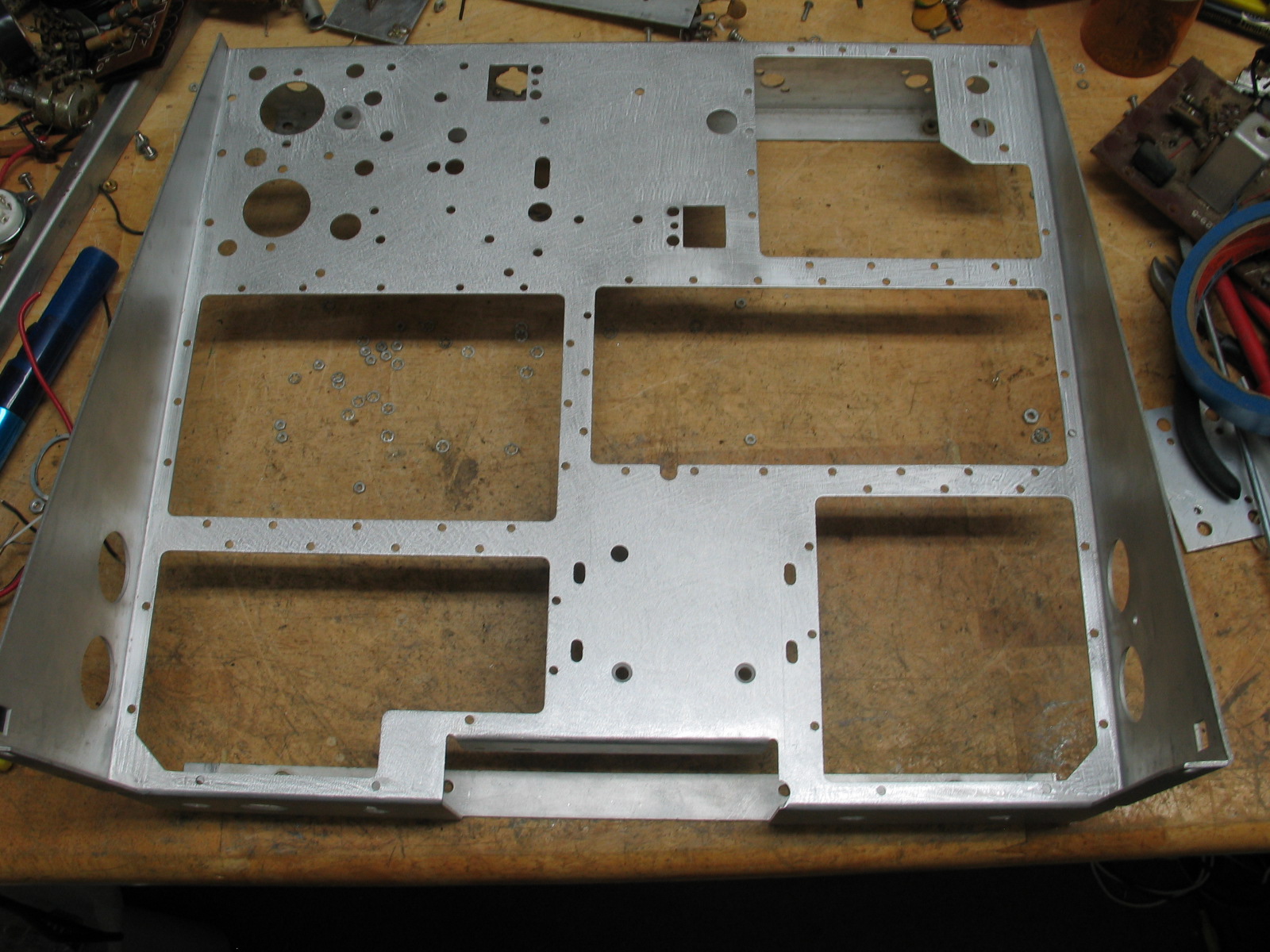
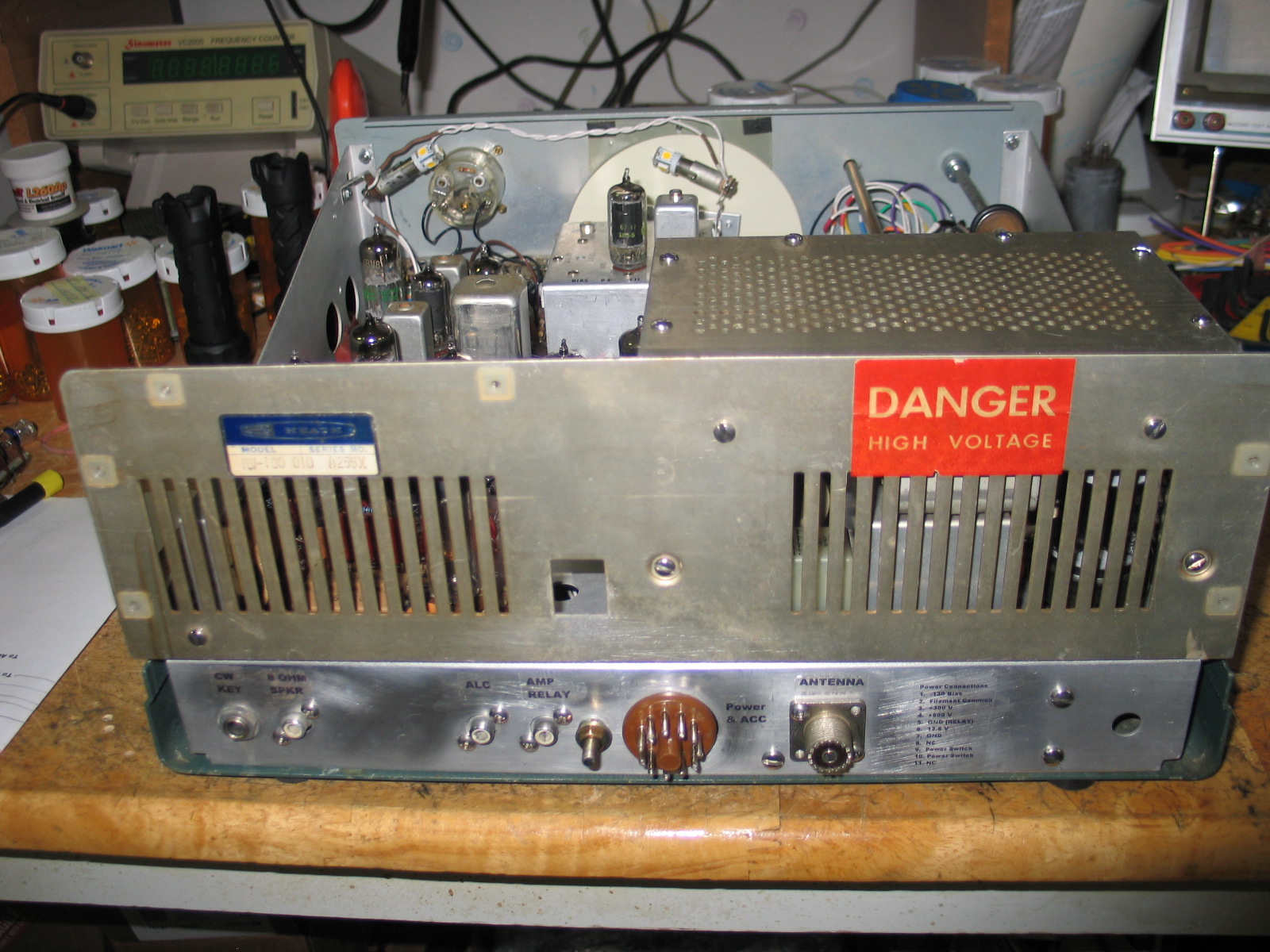
After sanding and rubbing down the chassis both above and below, the chassis looks like new. The sanding on the rear panel resulted in loss of the connector labels. No problem, I made new decals using MS Word and clear Ink Jet decal paper. Once the decals were made and applied, I then applied a coating of Polyurethane to protect the decals and preventing them from peeling off (the decals will peel off if you don’t coat them with Polyurethane).
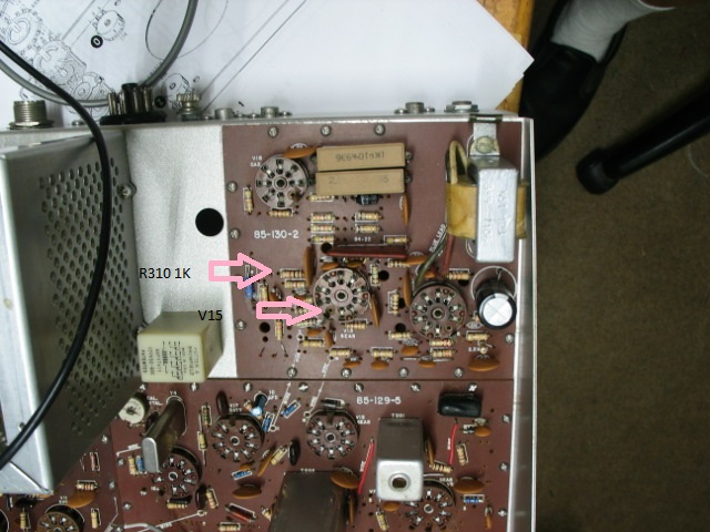
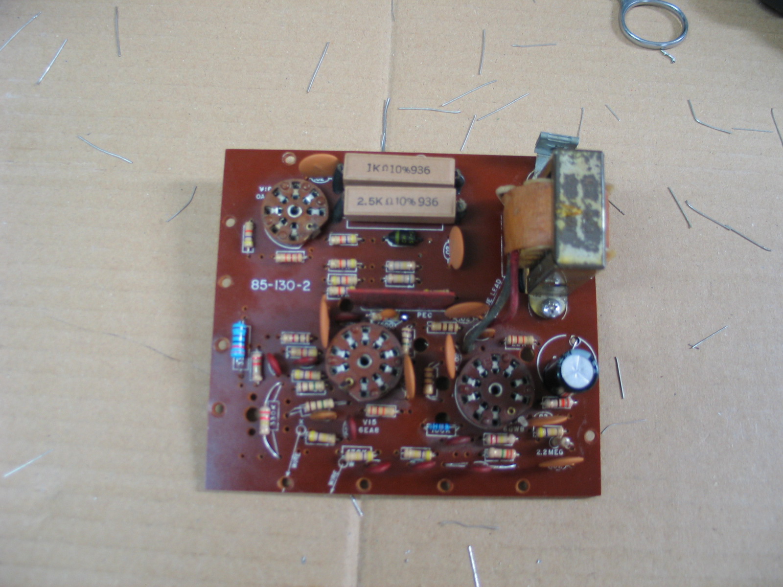
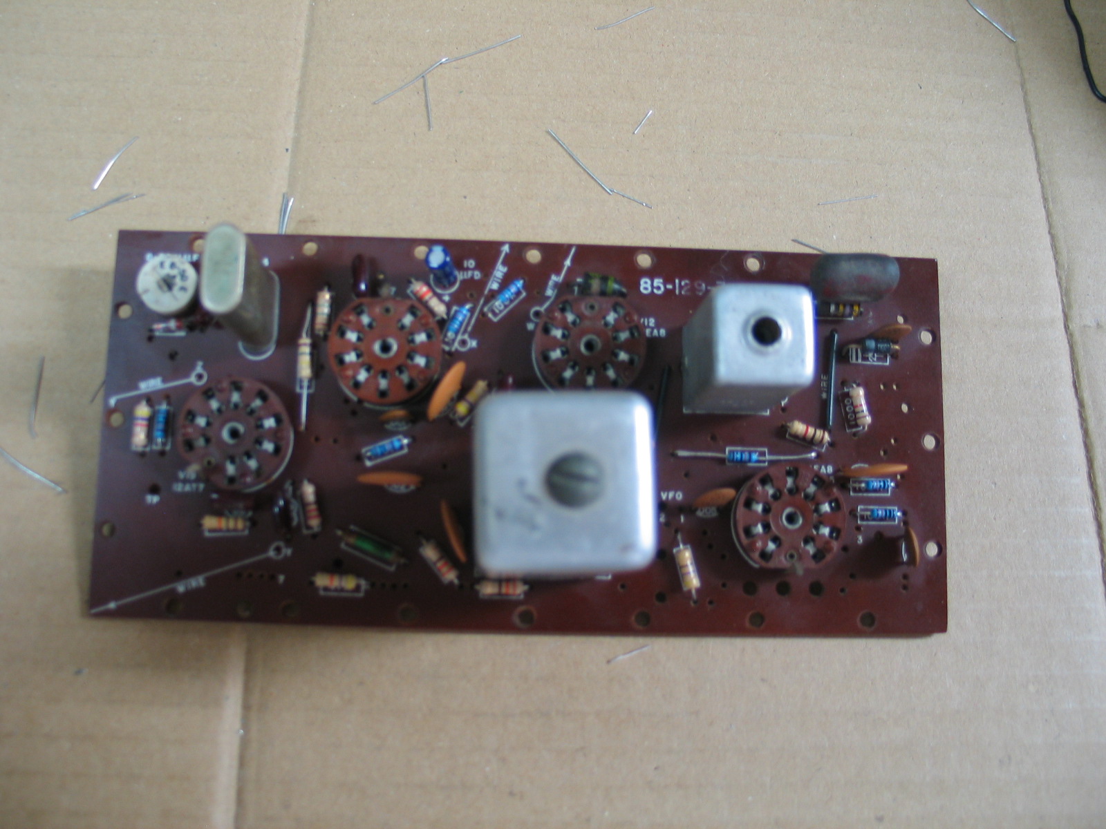
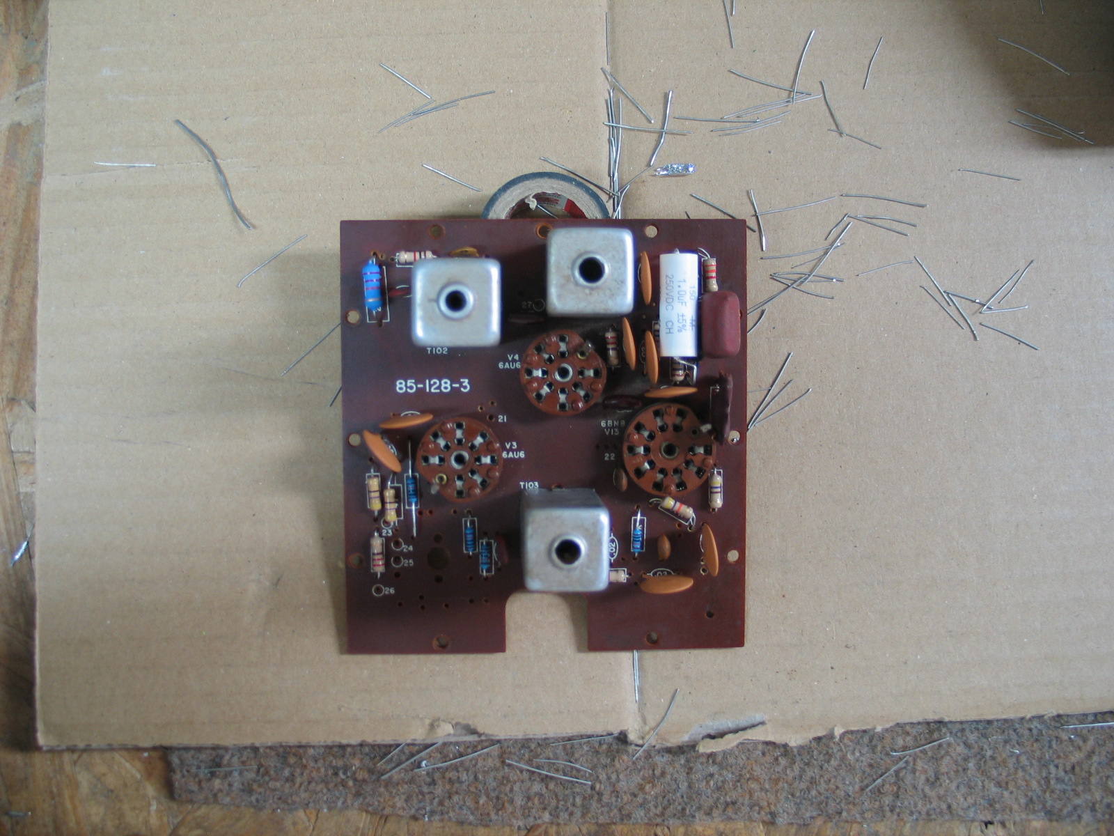
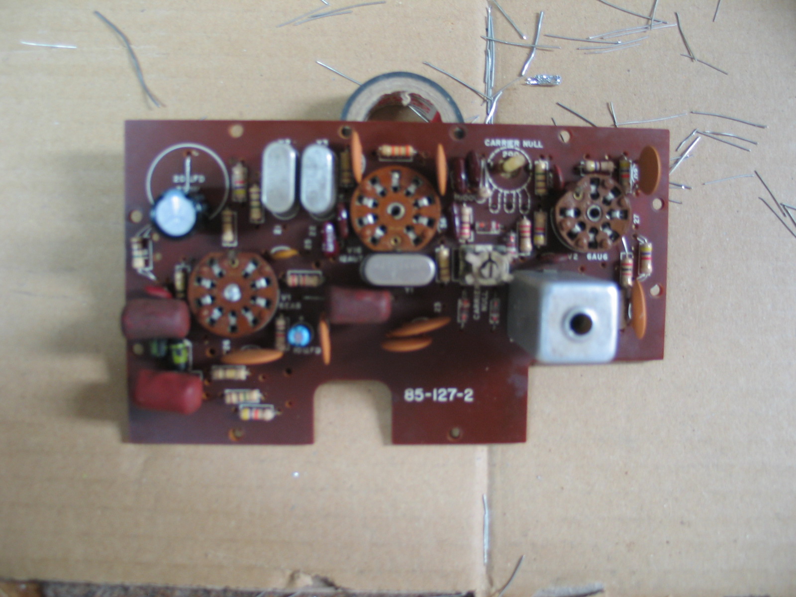
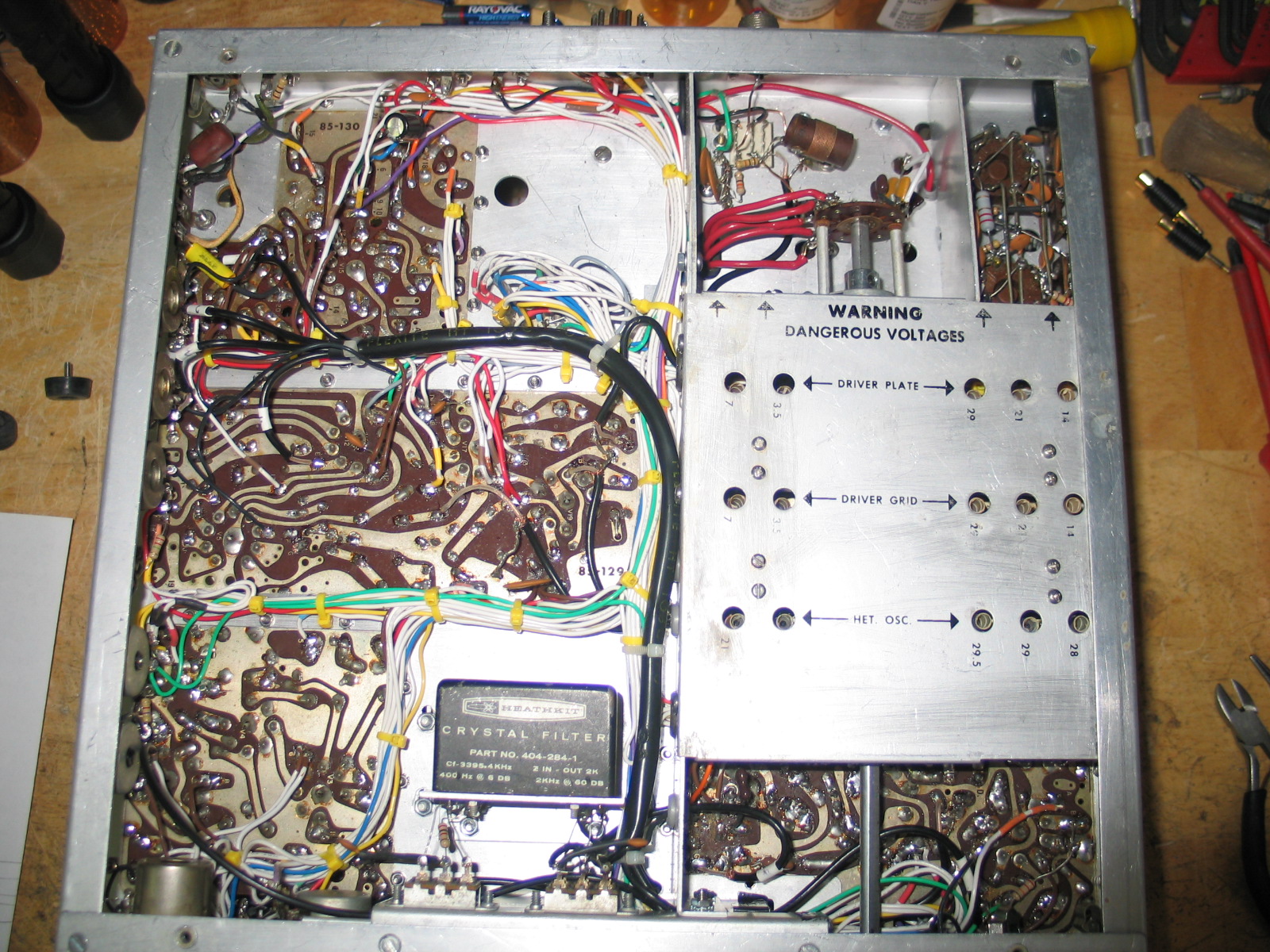
The 5 PC boards were rebuilt by stripping all resistors and 99% of all capacitors from each board. Each board was then cleaned with 409 and a soft brush. This brought out the White component silk screening making the boards look new again. The boards were then rinsed with clean water and allowed to dry. New resistors and disc capacitors were installed and the foil side edges were cleaned of corrosion and rubbed down with steel wool. All solder holes were cleared of solder. The “Solder Holes” must be clear for the wiring harness and other point to point wiring connections to be made. Excess solder, old components and wiring were removed.
The original wiring harness was usable but I wanted a new wiring harness. To produce a new wiring harness, I had to run all new wire. This meant I had to map and documented in an Excel spread sheet, each wire end to end as it ran throughout the original wiring harness. I laid the original wiring harness out on a piece of plywood and labeled each BO point (Break Out) as it appeared in the manual’s PICTORIAL 8-4A.
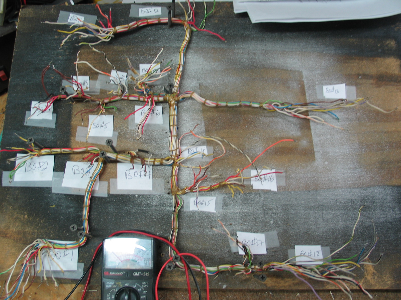
Each wire was mapped end to end using an Ohm meter and documented in an Excel spread sheet. Each entry in the spread sheet indicated wire color, start BO# and ending BO# just as the wires in the original wiring harness appeared in the HW-101 assembly manual’s Pictorial 8-4, 8-4A and 8-5. This was a very time consuming process, took between 2 and 3 weeks. Once the harness was completely mapped and documented in an Excel spread sheet, I repeated the process except this time I used the spread sheet and Pictorial’s 8-4 and 8-5 to compare/verify each wire in the new harness was mapped correctly. Any errors found were corrected and the spread sheet updated.
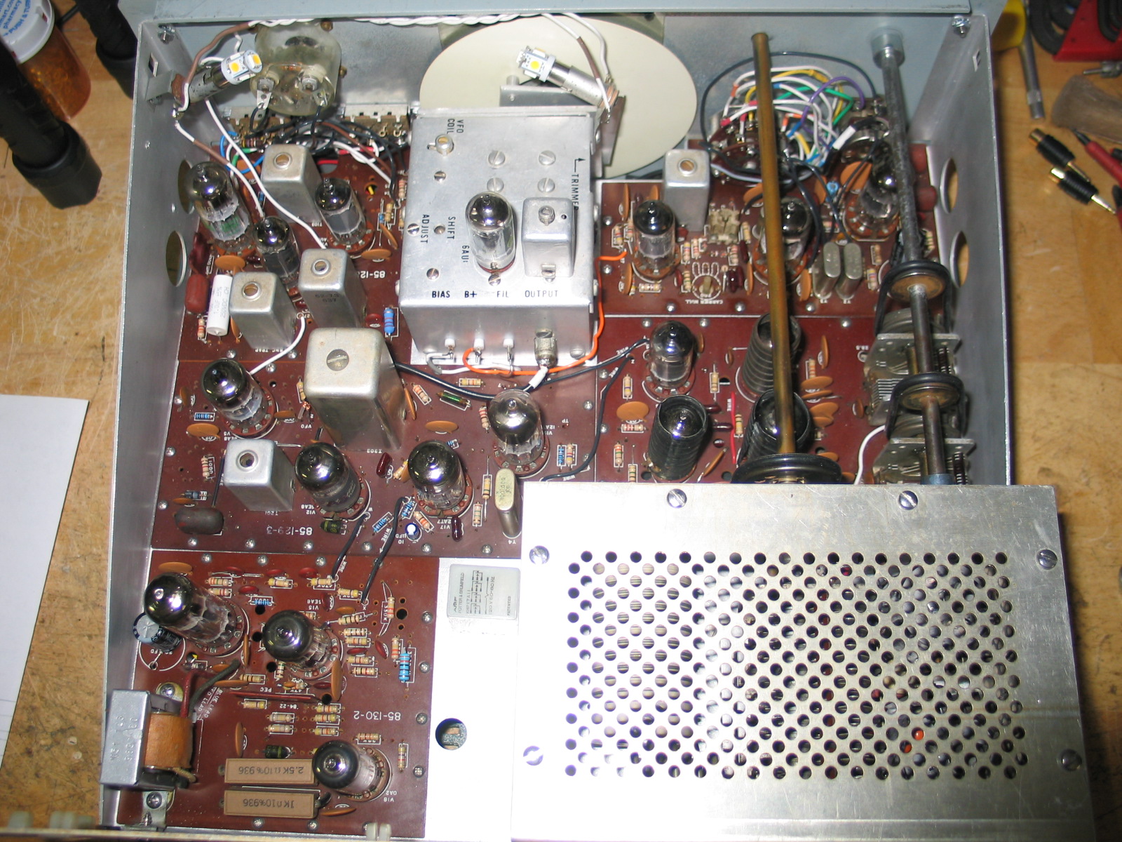
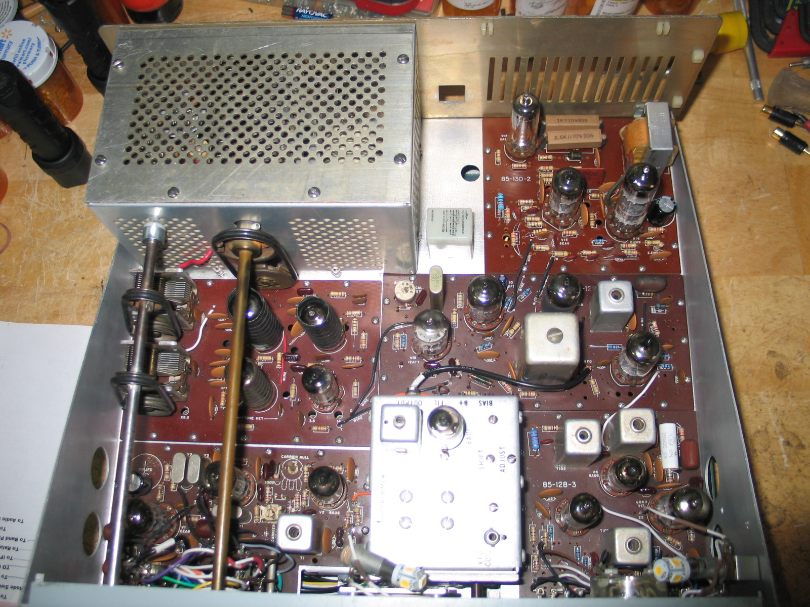
Assembly started by installing the support brackets, final amp enclosure “U” section, and other mechanical parts. The 5 rebuilt PC boards were then installed along with rear panel sockets and new 11 pin power connector. New RL1 and RL2 120 volt 4PDT relays were mounted. I used new mounting hardware for the brackets and PC boards.
The remaining assembly steps took about a month to complete. Running new RG-174 coax cables, making all the connections, mounting rear and front panel brackets, and checking for shorts in the new wiring, took quite a bit of time, a lot more then the original assembly required in an HW-101 original kit assembly.
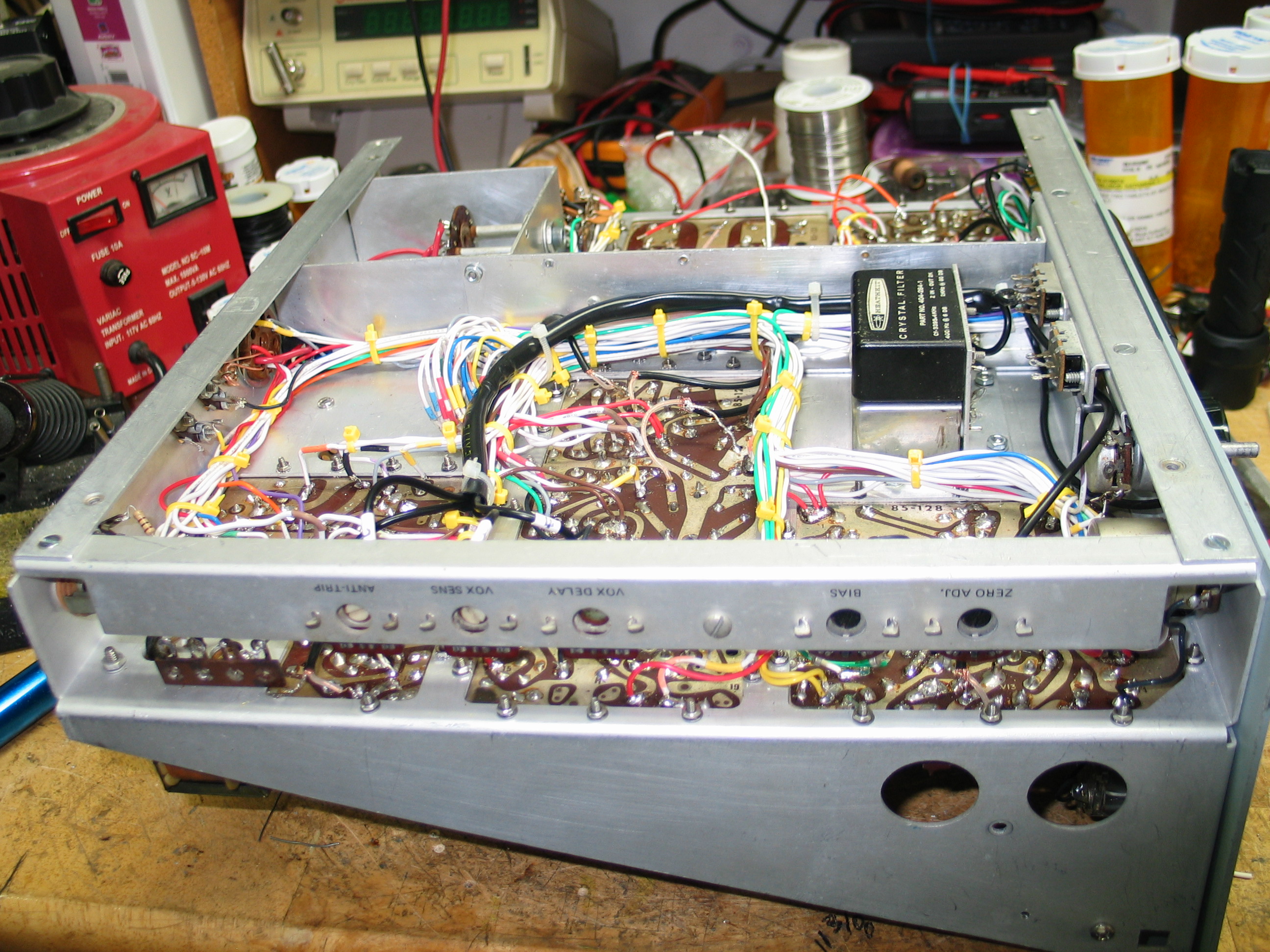
New decals were made for the rear apron. The decals were made using MS Word. The fonts were sized until they were as close to the original font size as possible. The file was saved then printed onto Clear Ink Jet decal sheet. Once the printed decals had thoroughly dried, Testors decal protection was applied and allowed to thoroughly dry at which time each decal was applied to the rear apron. Once the decals dried, a coating of polyurethane was applied by a brush and allowed to dry. I sprayed polyurethane onto a small brush then gently brushed over each decal. This sealed and prevented the decals from “lifting” off the rear apron.
The transceiver initial resistance checks were performed, only 2 errors were found, 2 missing wires. The wires were installed, the test repeated with success. Another error was caused by an original C10 4.7pdf capacitor that failed. C10 caused the S Meter (METER switch set to ALC) to peg fully to the right. I replaced C10 with a 5pfd mica cap solving the problem.
The transceiver operates like a brand new HW-101. Stability is excellent, takes only 2 to 3 minutes at most for it to stabilize. I have made numerous CW contacts, each contact provided excellent reports. One station said my signal was “Rock Solid”, meaning no drift or instability. Each contact lasted about 20 minutes. I powered up the transceiver this past weekend for 2 hours. I listened to one station for an hour and during that hour the radio did not exhibit any noticeable drift.
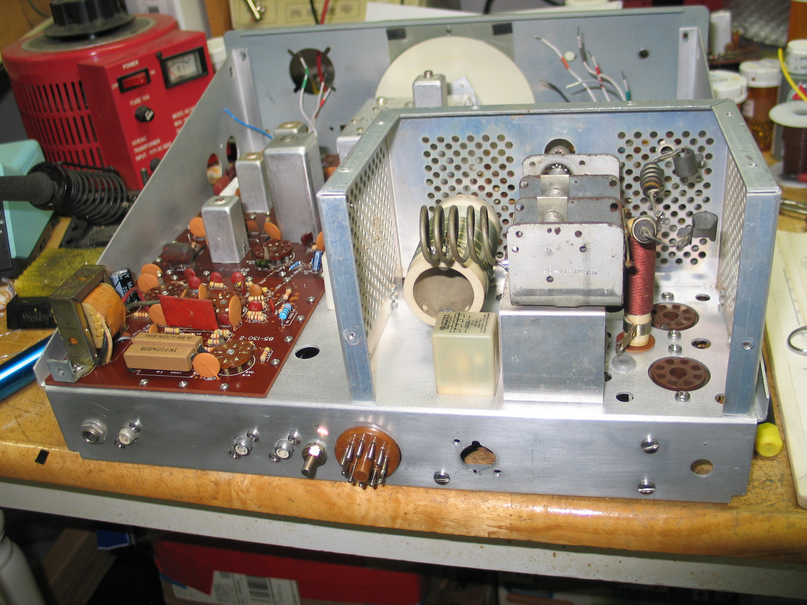
The following pictures show various top, bottom, and rear views of the fully restored HW-101. The first picture shows 2 added grounds to the inner Aluminum comb. I used #6 ground lugs bent at 90 degrees. I drilled two 3/32 hole in the inner comb. The holes were drilled so the other end of the ground lug would rest “flush” against the steel shield. I used a 4-3/8 sheet metal screw to secure the ground lug to the Aluminum comb. I soldered the other end to the steel shield, providing a solid metal to metal connection and additional support at the inner comb for the shields.
Update 19 Dec 2018
I was hearing some popping and crackling in the speaker in both receive and sometimes in transmit after a few minutes warm up. I wasn’t sure what the problem was. I checked for shorts in the wiring by “jiggling” the wiring on the MODE switch, rotated the band switch a few times, but none of that stopped the popping and crackling. I thought, since I hear it in both transmit AND receive, the problem could possibly be coming from V14, 6GW8 tubes? V14A is biased to cut off in transmit but V14B is not. Therefore since I can hear the noise in transmit then it was quite possibly a bad V14 6GW8 tubes. I pulled V14 from my SB-100 and put in the HW-101 build. I powered up the HW-101 and let it sit for 20 minutes or so. I no longer heard the popping and crackling in either receiver or transmit. I have ordered a replacement 6GW8 to put in the SB-100.
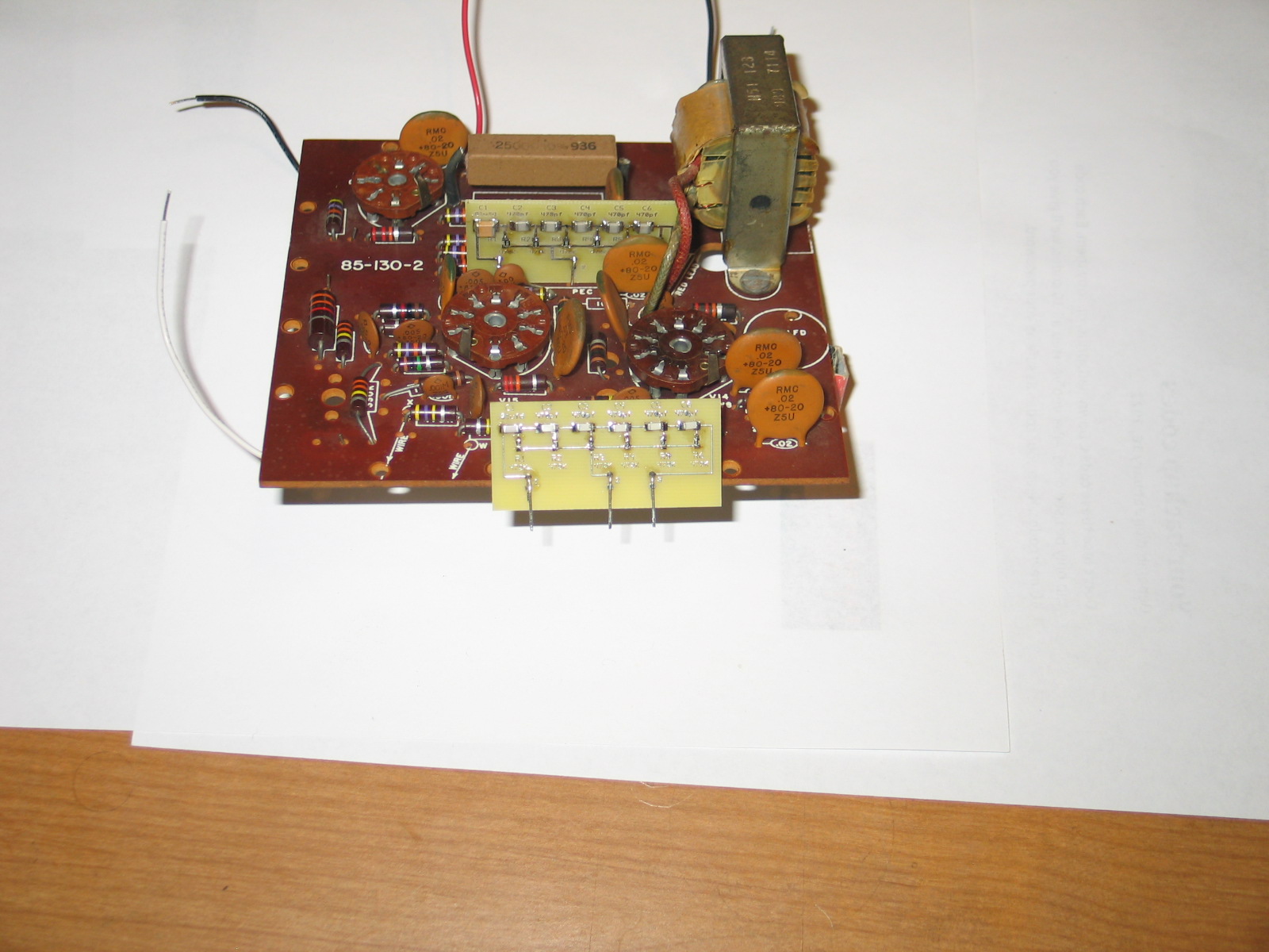
For those P.E.C. components that have a broken mounting pin too close to the P.E.C. body, I designed a replacement P.E.C. board using ExpressPCB CAD software. The P.E.C. PC board with populated SMD components fits perfectly in the original space the P.E.C. component mounted on the rear audio board in the HW-101. I’ve tested the P.E.C. board mounted on an HW-101 audio board and it works perfectly. The SMD component values are from top left to right.
C1 x 0.01ufd, C2 thru C6 are 470pfd 350VDC.
Bottom left to right R1 thru R6 470K 1/2W.
The number of components is different than what the schematic shows but the board works perfectly. It’s easy to reduce the number of components by simply connecting jumper wires in place of the SMD component.