Skip to content
Collins Collection
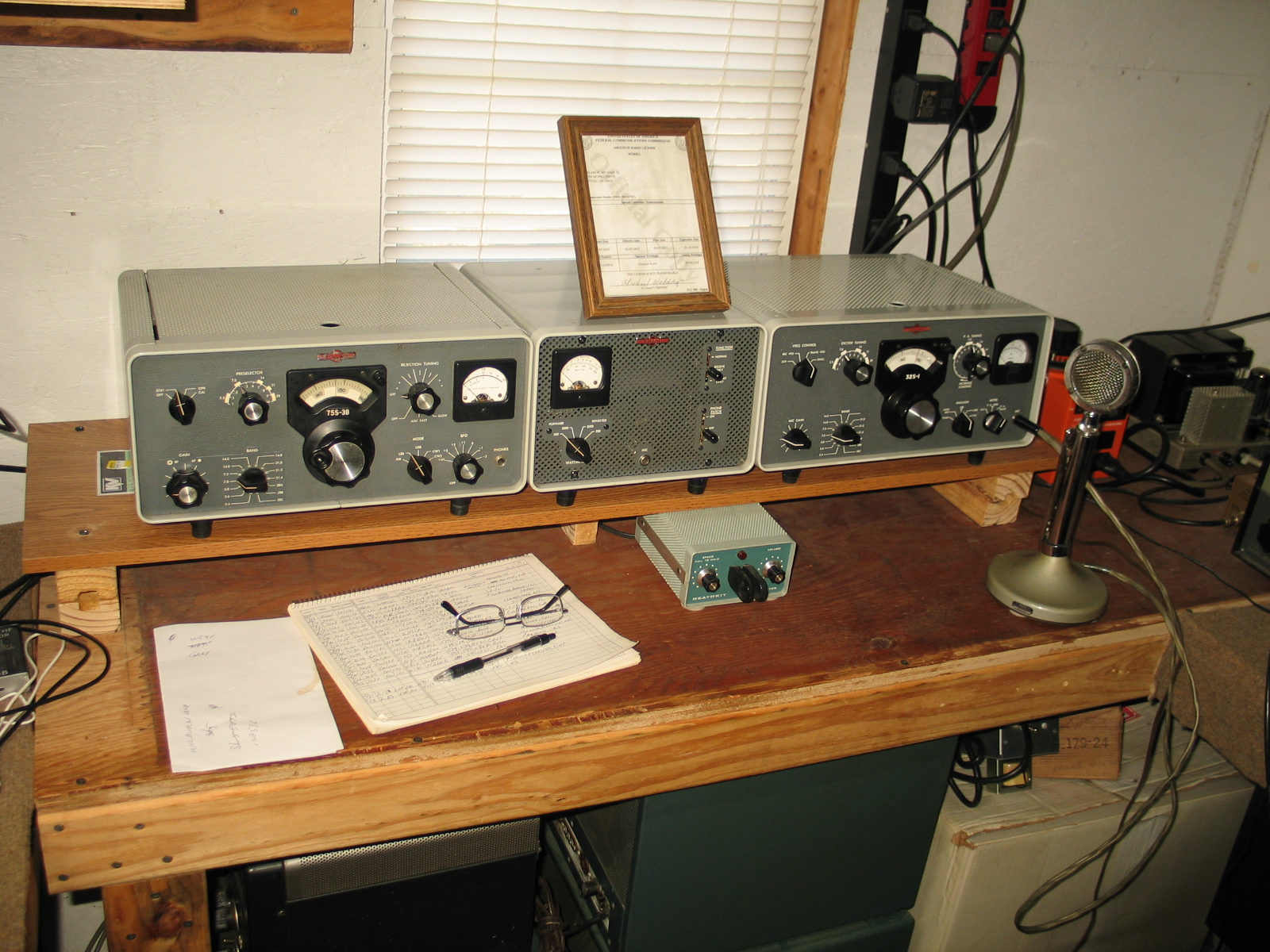
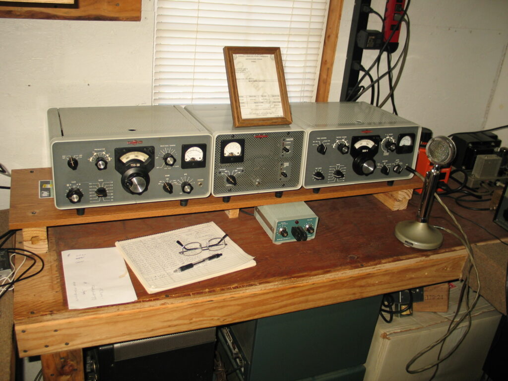
75S-3B Receiver, 32S-1, and 312B-4 Console
The 75S-3B receiver is on the left, 312B-4 Console is in the middle, and the 32S-1 transmitter is on the right. The transmitter’s 516F-2 power supply can be seen to the right of the Red Variac. The microphone is a non-amplified D-104. The transmitter’s RF output is fed to the 312B-4 console’s RF watt meter’s directional coupler and the console meter lamp is lit by the 6.3V on the transmitter’s rear apron.
I use a momentary N.O. SPST foot switch plugged into the 32S-1 rear apron “PTT” socket to key the transmitter in CW mode. I don’t use the 32S-1 VOX “CW Break-in”. I manually control the length of time the transmitter is keyed using the foot switch.
The Heathkit HD-1410 Keyer is connected the transmitter’s “Key” socket and works perfectly.
Collins 516F-2 Power Supply
I bought this 516F-2 power supply from a ham in Texas. I replaced all of the caps including C1. I added a 0.068ufd 2KVDC capacitor in parallel with C1. This parallel capacitor with C1 brought the HV down from +1011VDC down to +940VDC. I did not solid state the power supply, it still operates with both rectifier tubes.

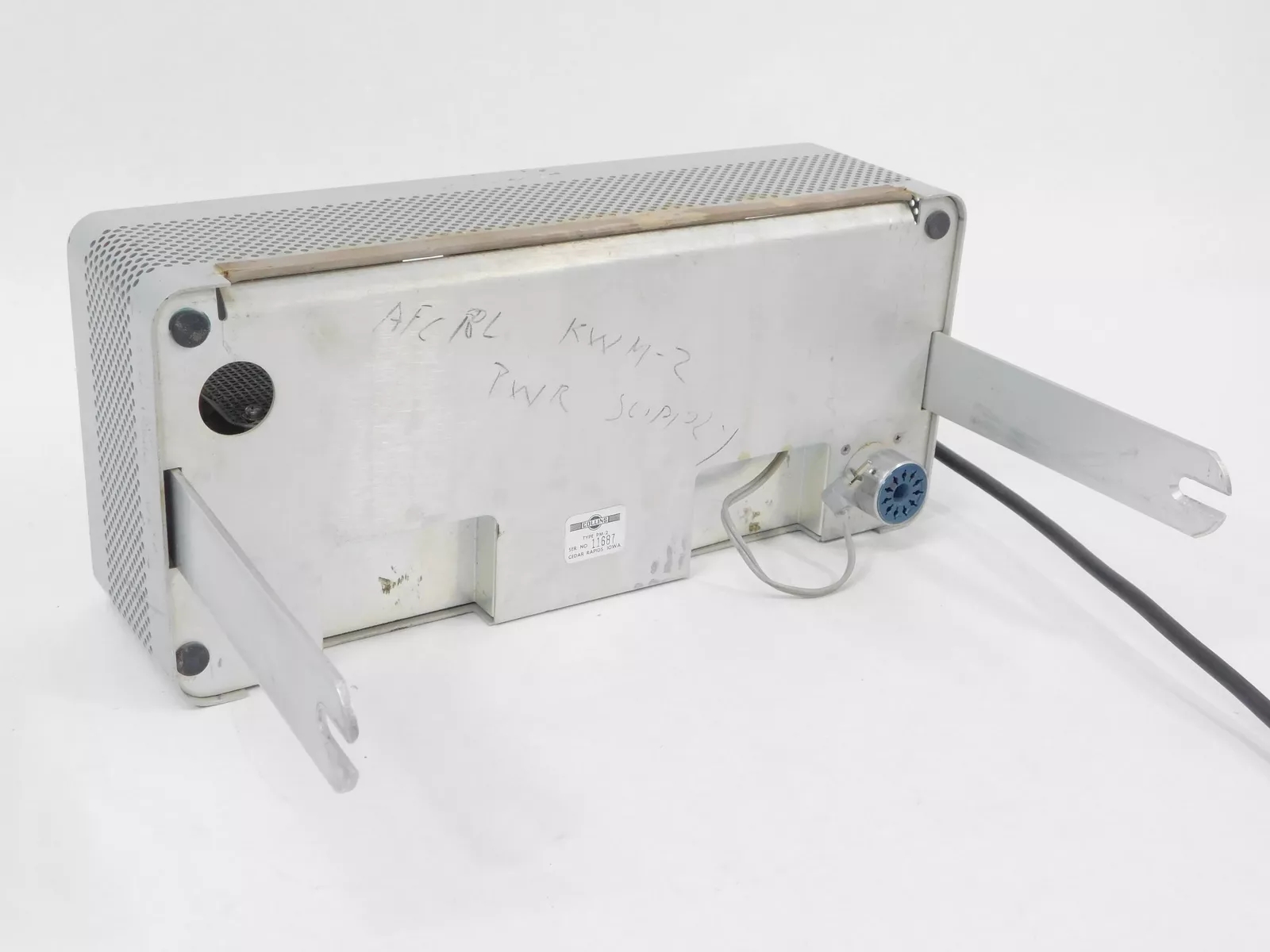
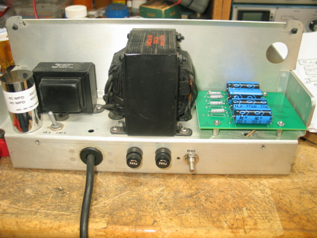
Collins PM-2 Power Supply
I picked up this PM-2 on eBay. The outward appearance is very good. The slides are straight, no extra holes have been drilled by previous owners, but a previous owners call sign and radio model was written in lead pencil. This PM-2 is a later version.

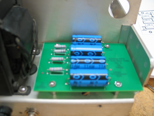
A previous owner had changed the HV filter capacitors. The HV filter capacitors were changed from 4 x 100ufd 350VDC to 3 x 22ufd at 450VDC. I’m not sure what that was suppose to accomplish. I didn’t take pictures of the wafer board’s original wiring. The picture below was taken of the wafer board after the HV section was cleaned up with new diodes, a new bias pot (original pot was bad), and new bias supply wiring. I kept the original bias diode and the 3 series resistors. I placed heat shrink tubing around the bias pot terminal.
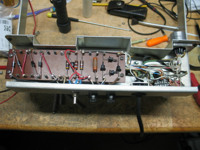
I replaced the old LV dual 40ufd can capacitor with a new dual 40ufd 450VDC can capacitor. I kept the 4 original diodes. I kept the 20ohm R5 resistor but replaced the 100K 2W R1 resistor with a new 100K 2W resistor. I designed a PC board that holds 4 x 100ufd 350VDC capacitors and 4 x 270K (R3, R4, R5, and R6) equalizing resistors. The PC board mounts in the space previously occupied by the small speaker and uses the same mounting holes the speaker support mounts used, no new holes were drilled. I replaced the speaker support hex mounts with 3/8″ dual female 4x40x1/2″ metal hex stand-offs. There are 3 connections to the PC board, the upper right corner is the board’s ground, a Red wire connects from C1s positive terminal on the left and the Brown HV transformer winding wire on the right. These 2 connections are not visible in the picture below. The 2 wire connections were made after the picture below was taken.
This PM-2 is the later version which has 4 x 100ufd at 350VDC in the HV filter section. A previous owner messed with the HV supply filter capacitors.