Skip to content
Drake Collection
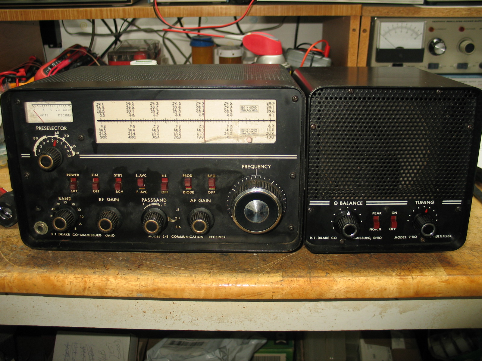
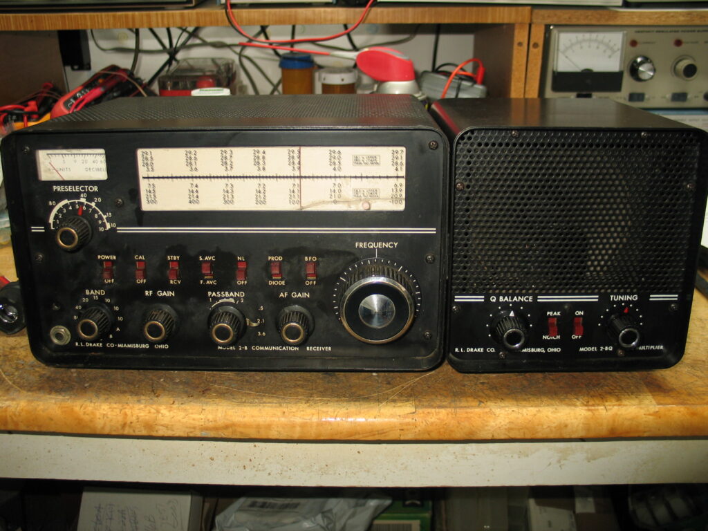
Drake 2B with 2B Q-Multiplier and 2B 100Khz Calibrator
Picked this 2B up on eBay. The seller said the audio was distorted. I’ve ordered the Drake 2B capacitor kit from hayseedhamfest.com. The 2B capacitor kit arrived so now I have to take the time and use it to replace the original filter capacitors.
The S meter was out of calibration so I adjusted the S meter zero and S meter adjustment on the rear, S meter works very well now. This receiver is very stable after a 1 minute warm up. The main tuning shaft is bent so I need a replacement. I found and purchased the parts from a ham in Texas. They arrived earlier this week.
The front panel RED slide switches can, over time, become difficult to slide. I used DeoXit F5 Fader cleaner / lubricant applied to the switches behind the front panel then applied same F5 cleaner/lubricant to each slide switch through the “front” panel. I placed the F5 spray can output tube pointed at the slide switch handle and gave it a shot of cleaner. I worked the switches and that made each slide switch moved freely.
I applied WD-40 Contact Cleaner to the Passband wafer switch and to each band switch wafer so the switches worked properly. I used DeoXit F5 Fader Cleaner/Lubricant to each pot making them rotate freely and without static noise. I notice that the Passband switch would intermittently stop working. I found a loose wire on the Passband wafer switch assembly that had never been soldered from the factory. Applied some solder fixed that intermittent Passband problem.
For a receiver that’s 65+ years old it works very well.
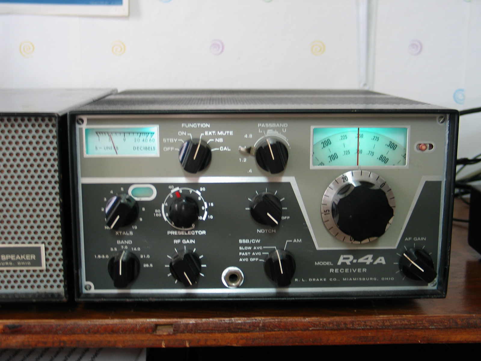
Drake R4A
I picked this R4A up on eBay. The power transformer was shorted so I had Hayboer Transformers in Grand Haven, Mich make me a new one, price $85 + shipping.
I ordered and install the Drake R4A capacitor kit from Hayseedhamfest. Receiver works great.

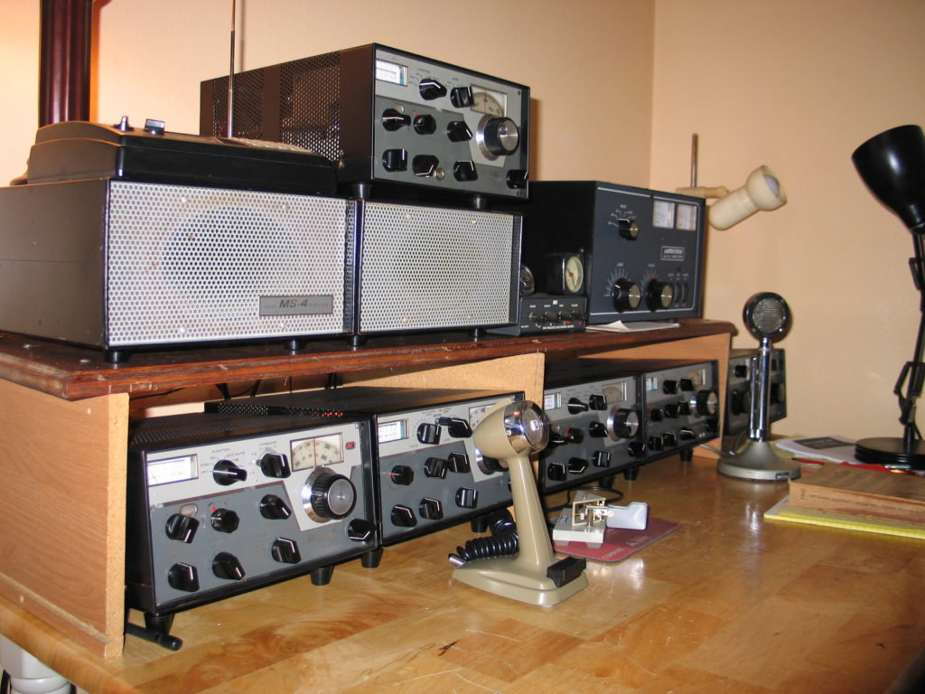
These are old pictures of my Drake collection prior to obtaining the above R4A and 2B receivers. The R4C sitting on top of the AC4 speaker enclosure has been sold since this picture was taken. The other R4C below is fully loaded with filters and Sherwood upgrades/mods.
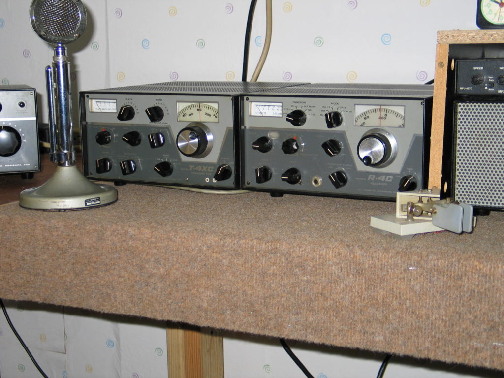
T4XC / R4C Twins
The T4XC has a 12VDC small muffin fan mounted on the rear that blows air into the final amplifier. Power for the fan is obtained through a 1/2 wave rectifier mounted below the chassis and tapped off the 12VAC filament source. The fan runs continuously while the transmitter is powered ON. It’s very quiet and keeps the final amplifier and driver stages cool during transmit.
I picked up this R4C while I worked for General Dynamics in Vaihingen Germany. I found it at the Friedrichshafen Germany’s hamfest which is equal to Dayton Ohio’s Hamvention. I paid $125 for it and it was “like new”. I ordered and installed the following INRAD filters, and Sherwood mods/upgrades.
INRAD:
6Khz GUF-1, AM (6Khz), 2 SSB (one factory Drake SSB and one INRAD SSB 2.1Khz), and 2 CW (500hz and 250hz)
SHERWOOD:
Solid state 3rd Mixer, R4C Audio Amplifier, R4C New Replacement Power Supply Board
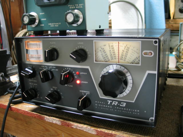
TR-3 80 to 10 meter transceiver
This is my recent acquired Drake TR-3 transceiver. It appears to be in very good condition. The bottom right front corner is bent. I bent it back into shape. I have a Drake AC-3 power supply that will provide power for it. The AC-3 power supply capacitors have been re stuffed with new capacitors and all the diodes and resistors were replaced with new components.
During power up, resistor R111 in the TR3 overheated due to a shorted C145B (60ufd 250VDC) capacitor also in the TR3. C145B is one of 3 capacitors in the only can capacitor in the TR3. I replaced C145 with the hayseedhamfest TR3 capacitor kit and R111 was replaced with a new 3.3K 1/2W resistor. Power up resulted in no receive. I found 2 causes for loss of receive. One, was the ground on the RV3 remote VFO socket pin “8” was missing and R4 100 ohm 5W resistor in the AC3 supply was “Open”. Fixed both problems and the TR3 came to life.
I mounted a 12VDC muffing fan to the rear of the final amplifier enclosure. I ran the fan’s RED wire through one of the dial lamp switch screw holes to a half wave rectifier. The fan’s Black lead connects to one of the chassis sheet metal screws. The rectifier consists of a 10ufd 35VDC axial lead capacitor and a single diode connected at one end of the filament fuse, no on the filament side of the fuse. The fan runs constantly and at a speed sufficient enough to keep the final tubes cool. The fan is not noticeable when the TR3 is powered on.