Skip to content
Collins 516F-2
Power Supply Rebuild
I rebuilt this Collins 516F-2 power supply.
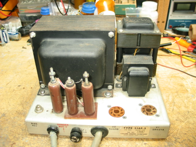
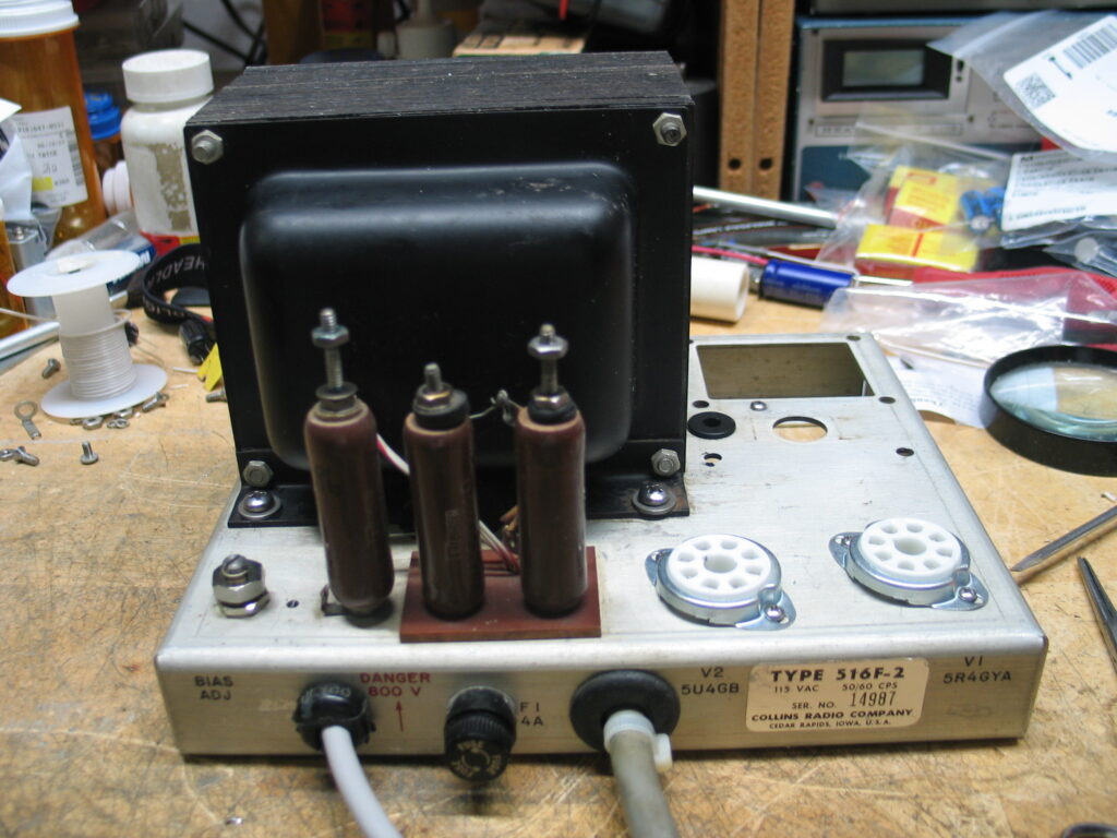
Top view before rebuilding. The perforated cover over wire wound resistors R4, R5, and R6 was missing when I purchased the supply.
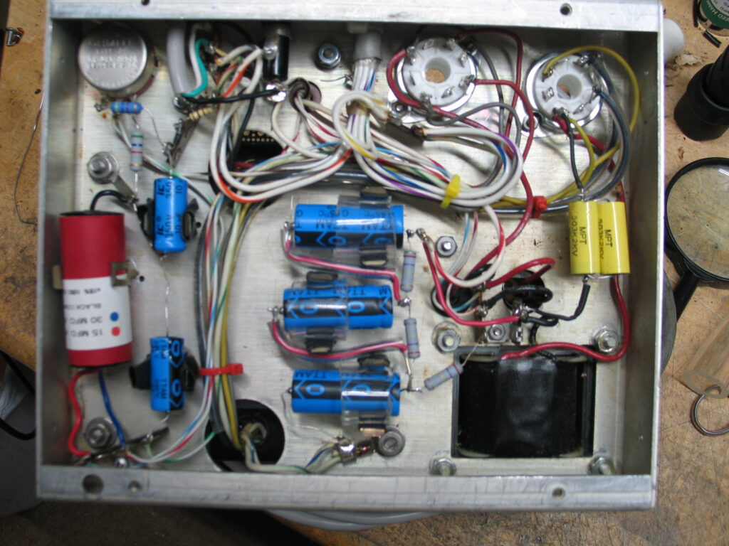
Original Below Chassis view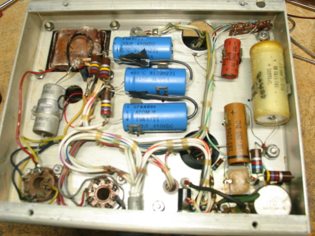
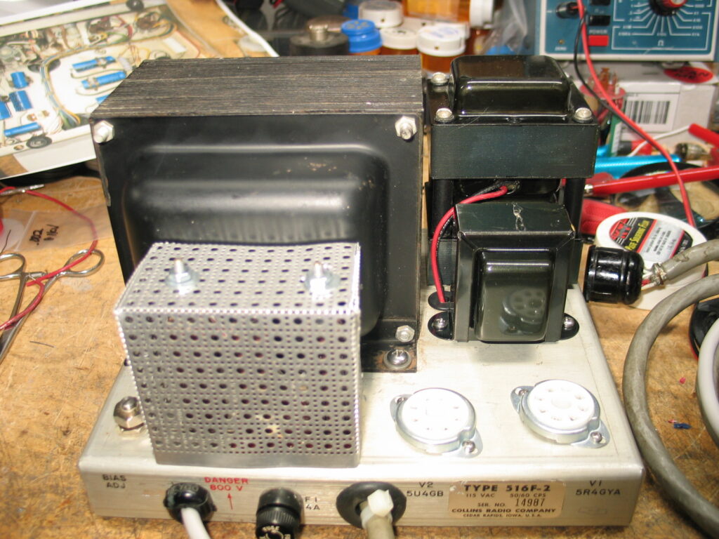
Top View After Removing chokes and clean up of dirt and grime around the power transformer and choke area.
New replacement L1, L2, and L3 chokes have been ordered. The original tube sockets were replaced with new Ceramic octal sockets. The Bias pot was replaced with a new pot.
Home made replacement cover over R4, R5, and R6 wire wound resistors made from perforated Aluminum bent to fit.
New L1, L2, and L3 chokes purchased from National Radio LLC are installed.
I decided not to solid state the supply.
A new 3 wire power cord replaced the original cracked 3 wire power cord. I reused the original power cord strain relief.
A length of clear Nylon tubing was slid over the entire length of each V1 HV secondary Blue wires. The clear Nylon tubing provides an additional amount of insulation to the old aging and sometimes cracked power transformer’s HV secondary Blue wires to help prevent arcing between the 2 Blue wires and the chassis.
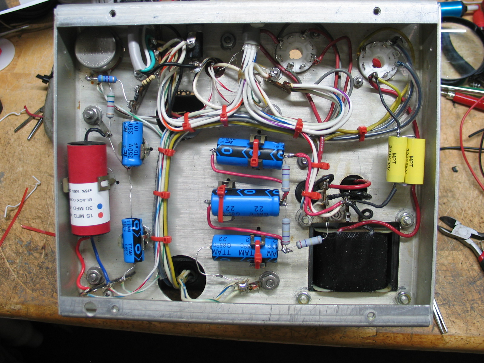
I mounted and secured the new C2, C3, and C4 capacitors in the clamps as shown in the picture below. DO NOT DO THIS!!! Scroll down to see why!!!

I first tested the LV supply with only the V2 5U4GB rectifier tube installed. All went well no problems. The DMM measured no-load voltage of approximately +365VDC on the 11 pin power socket pins 1 and ground on pin 10. I powered down the supply and waited a minute while monitoring the LV at pin 1 and ground to drop to zero, took about 10 seconds.
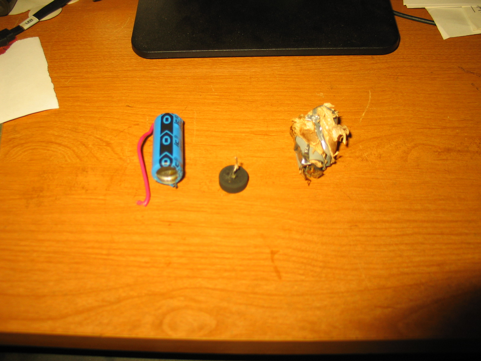
Next, I then plugged the 5R4GYB rectifier tube into its socket, connected the DMM to pin 2 and pin 10 ground. I powered up the supply and when V1 5R4GYB HV rectifier tube started conducting I heard hum that didn’t happen during LV test. Before I could turn the power supply OFF, C2 exploded resulting in a very loud POP with lots of White smoke and capacitor C2 was permanent damaged as shown in the picture below.

What caused C2 to explode? A small “tear” through capacitor C2’s thin plastic covering created a “short” between C2’s body and the metal clamp to ground.
The voltage applied to C2 is 1KVDC and due to the short to ground through the thin plastic covering, C2’s maximum voltage rating was significantly exceeded causing C2 to explode.
The thin plastic covering over modern day capacitors is NOT designed to provide insulation to prevent shorts!!! The plastic covering over the capacitors is to provide capacitance value and voltage rating information ONLY.
The fix is.
Cut 1″ lengths of 1″ OD x 3/4″ ID PVC tubing available at your local hardware store. Slide each capacitor into the tubing. The tubing with capacitor is then pressed into each metal clamp, centering the tubing in the metal clamp and capacitor in the tubing. C4 doesn’t need the tubing as it’s metal body is already at ground but I used the tubing to provide additional mechanical support for C4 in the metal clamp.
I also used small diameter PVC tubing available at your local hardware store. I cut the tubing length and slid the PVC tubing over the interconnecting wires between capacitors C2, C3, and C4. The small PVC tubing provides additional insulation between the interconnecting wires and the chassis.
I use thick heat shrink tubing over the metal clamp fingers for added insulation between capacitor’s C6 and C7, and the metal clamps.
I DO NOT recommend using cable ties to “squeeze” the metal clamps tight around the capacitors. The PVC tubing around the capacitors is more than enough to secure the capacitors firmly in place in the metal clamps.
The typical no-load HV output voltage at pins “2” and “10” on the 11 pin power socket with 115VAC primary AC power is +1013VDC. I replaced C1 with a pair of 0.05ufd 2KVDC capacitor connected in parallel. The HV no-load output voltage as measured at pins 2 and 10 is now measured at +920VDC.
I replaced the Selenium rectifier with a 1N4007 1KVDC diode.
I replaced the bias pot with a new 5K pot and replace both R8 and R10 fixed resistors with new resistors.
Capacitors C5A and C5B were replaced with a new dual capacitor from National Radio LLC. You may not need to replace your bias pot, mine had a bad spot that couldn’t be fixed with contact cleaner.
I replaced both wafer material rectifier tube sockets with ceramic sockets. I had to grind each tube’s mounting hole using a grinding tool so the socket would fit in the holes.
I also replaced the original V1 5R4GYA HV rectifier tube with a 5R4GYB rectifier tube. The “5R4GYB” tube has a higher per-plate DC voltage and current rating.
I have performed this update to both of my 516F-2 power supplies.
I power my 32S-1 transmitter’s 516F-2 supply and the 75S-3B receiver through a metal housed power strip plugged into a 20 amp Variac. The Variac is adjusted for 115VAC output. The receiver and transmitter power switches are left in the ON position and AC power to the power strip and S-Line is controlled by the Variac’s power switch. When the S-line is not in use the Variac power switch is left in the OFF position.
If you click the picture below, your Mouse will shows a “+”.
Click the picture again and the picture shows a close up of the clear PVC tubing over the 3 capacitors, the RED wires connecting the 3 capacitors C2, C3, and C4 in series, and the power transformer’s BLUE HV secondary wires connecting to V1’s tube socket pins 4 and 6. Use the Mouse “Wheel” to scroll UP and DOWN. Click and hold the horizontal bar on the bottom of the picture to move “LEFT” and “RIGHT”.
Place Mouse over the picture and click the picture again and the picture will zoom “out”.
Place Mouse either Left or Right outside of the picture and click “Left Arrow”. You will be returned to the normal display of the listing.