Collins Collection
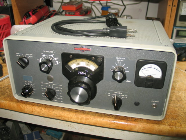
75S-1 Receiver
My 1959 75S-1 serial number 1036. Bought it on eBay.
The S meter zero pot (250 ohm) was found to be toast. I replace it with a NOS 200 ohm pot and changed the series resistor from 68 ohms to 100 ohms, 18 ohms shy of the original circuit series resistance.
I replaced V7, 6AT6 which is the Detector, AGC Rectifier, and first audio amp. This brought the receiver to life.
I adjusted the meter zero pot and the RF Level pot. I calibrated the 100Khz calibrator using 15Mhz WWV as stated in the 75S-1 manual.
I believe the CW filter is the 250Hz filter as it is quite narrow.
Excluding the Rejection Tuning not working, the receiver is performing very well on AM, LSB, USB, and CW on all bands. Video link below to see the receiver on 40 meters at night. The antenna is a 40 meter dipole up about 28 feet.
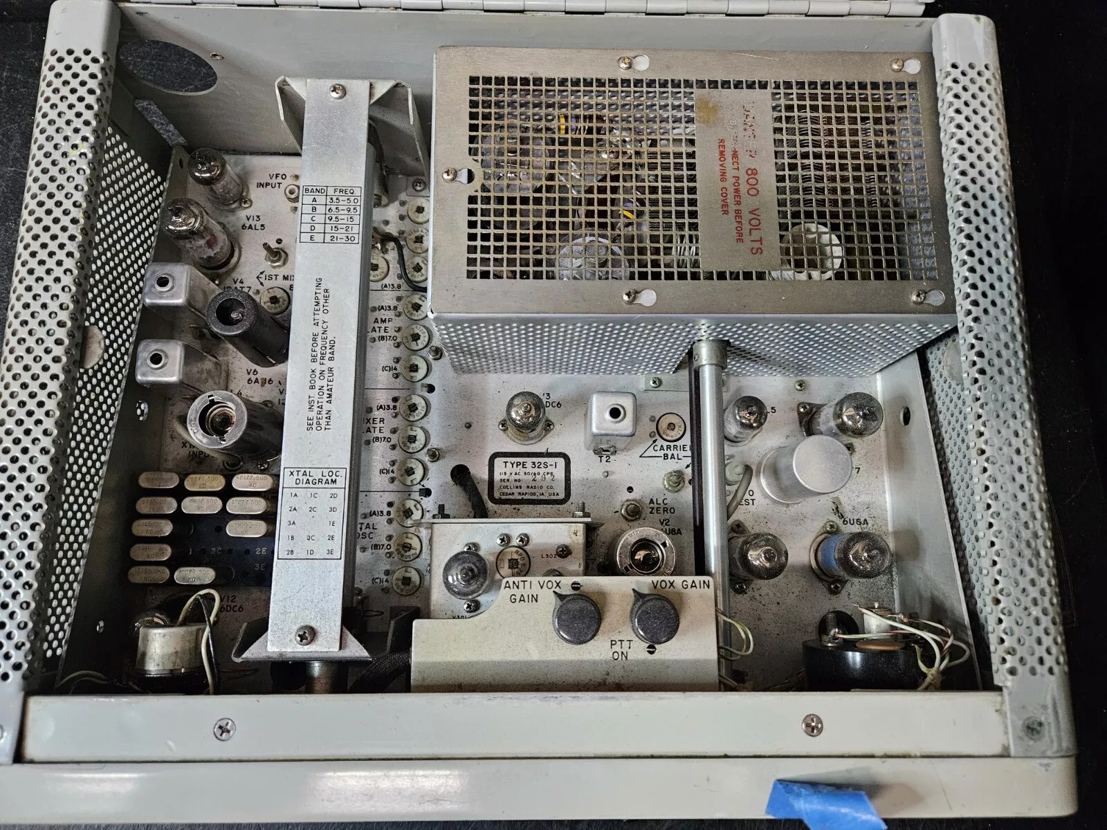
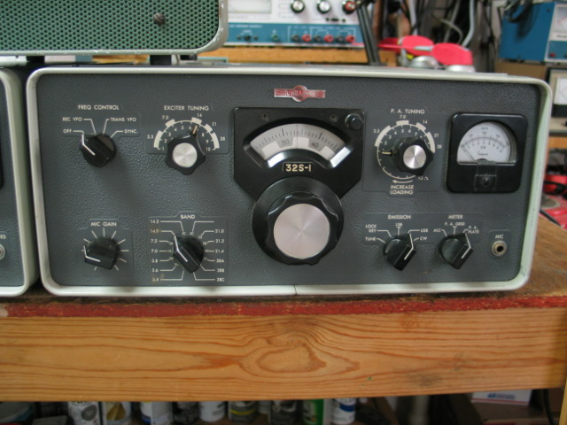
32S-1 Transmitter Serial Number 292
I picked this 32S-1 up on eBay. It appears to be in very good physical condition. There’s some dirt/dust on the chassis that needs to be cleaned up.
The P.A. Tuning shaft coupler set screw was loose causing the P.A. control to rotate 360. Tightened the set screw fixed that problem.
The EXCITER TUNING rotated but the slugs didn’t rise out of or back into the coil forms. I had this same problem with the above 75S-1 receiver. The rollers on both ends of the tuning assembly and the front ball bearings needed lubrication. I applied a small amount of “KROIL” using a cotton swab to the front and back rollers and to the front ball bearings. This fixed the EXCITER TUNING.
I haven’t powered up the transmitter yet. I want to give it a thorough visual inspection then perform some resistance checks first. If all goes well then I’ll power up the transmitter into a 50 ohm dummy load.

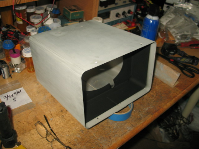
312B-4 Console
I picked up this 312B-4 Console on eBay. The paint is horrible. The front panel and the internal components are in excellent condition.

All internal components and front panel were removed and safely stored.
The internal front Flat Black was repainted. The console cabinet and front trim paint were removed using Citristrip paint remover. The cabinet and trim were prepared for painting.
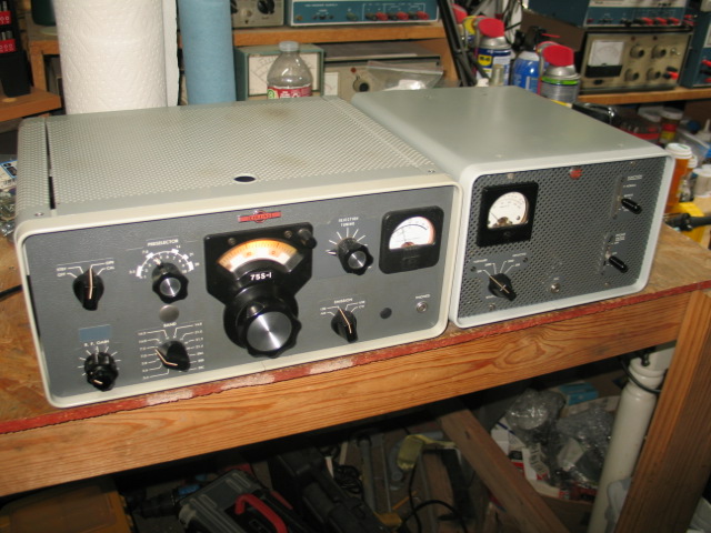
The finished repainted Collins 312B-4 Console cabinet and front trim along side my 75S-1 receiver.
Collins 516F-2 Power Supply
(1 of 2 of my Collins 516F-2 power supplies )
I bought this 516F-2 power supply from a ham in Texas. It’s all original and in excellent physical condition. I plan on replacing all of the electrolytic capacitors to bring it up to modern specs. It needs a bottom cover plate.
I picked up a second Collins 516F-2 power supply that will be rebuilt.

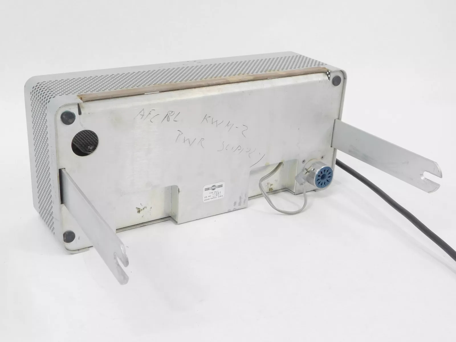
Collins PM-2 Power Supply
I picked up this PM-2 on eBay. The outward appearance is very good. The slides are straight, no extra holes have been drilled by previous owners, but a previous owners call sign and radio model was written in lead pencil. This PM-2 is a later version.

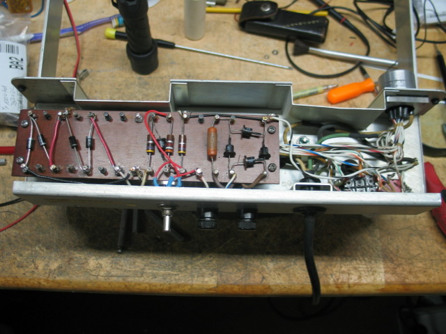
A previous owner had changed the HV filter capacitors. The HV filter capacitors were changed from 4 x 100ufd 350VDC to 3 x 22ufd at 450VDC. I’m not sure what that was suppose to accomplish. I didn’t take pictures of the wafer board’s original wiring. The picture below was taken of the wafer board after the HV section was cleaned up with new diodes, a new bias pot (original pot was bad), and new bias supply wiring. I kept the original bias diode and the 3 series resistors. I placed heat shrink tubing around the bias pot terminal.
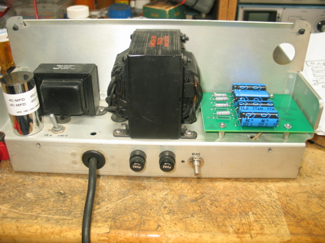
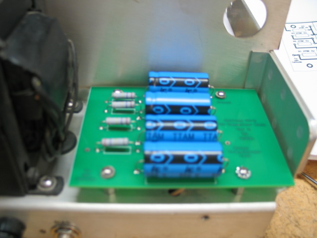
I replaced the old LV dual 40ufd can capacitor with a new dual 40ufd 450VDC can capacitor. I kept the 4 original diodes. I kept the 20ohm R5 resistor but replaced the 100K 2W R1 resistor with a new 100K 2W resistor. I designed a PC board that holds 4 x 100ufd 350VDC capacitors and 4 x 270K (R3, R4, R5, and R6) equalizing resistors. The PC board mounts in the space previously occupied by the small speaker and uses the same mounting holes the speaker support mounts used, no new holes were drilled. I replaced the speaker support hex mounts with 3/8″ dual female 4x40x1/2″ metal hex stand-offs. There are 3 connections to the PC board, the upper right corner is the board’s ground, a Red wire connects from C1s positive terminal on the left and the Brown HV transformer winding wire on the right. These 2 connections are not visible in the picture below. The 2 wire connections were made after the picture below was taken.
This PM-2 is the later version which has 4 x 100ufd at 350VDC in the HV filter section. A previous owner messed with the HV supply filter capacitors.