Lafayette KT-200 Complete Rebuild
This is not a Lafayette KT-200 receiver that has had a few capacitors and resistors replaced. This is a complete take down to the original Lafayette KT-200 “kit” form and rebuilt with all new capacitors, resistors, all new tube sockets, and all new wiring.
I picked up this Lafayette KT-200 4 band short wave receiver on eBay. It was in fair shape but the original kit builder skills were fair to poor.
I had to replace the ON/OFF volume control as the switch was bad.
The S meter is not original so I replaced that cheap CB S-Meter with a R390 Meter (see pictures and description below).
I replaced the broken Banana plug antenna terminals and repaired the speaker terminal strip by removing the RCA socket.
I have a reproduced KT-200 assembly manual which contains all the assembly steps and complete one page fold out pictorials.
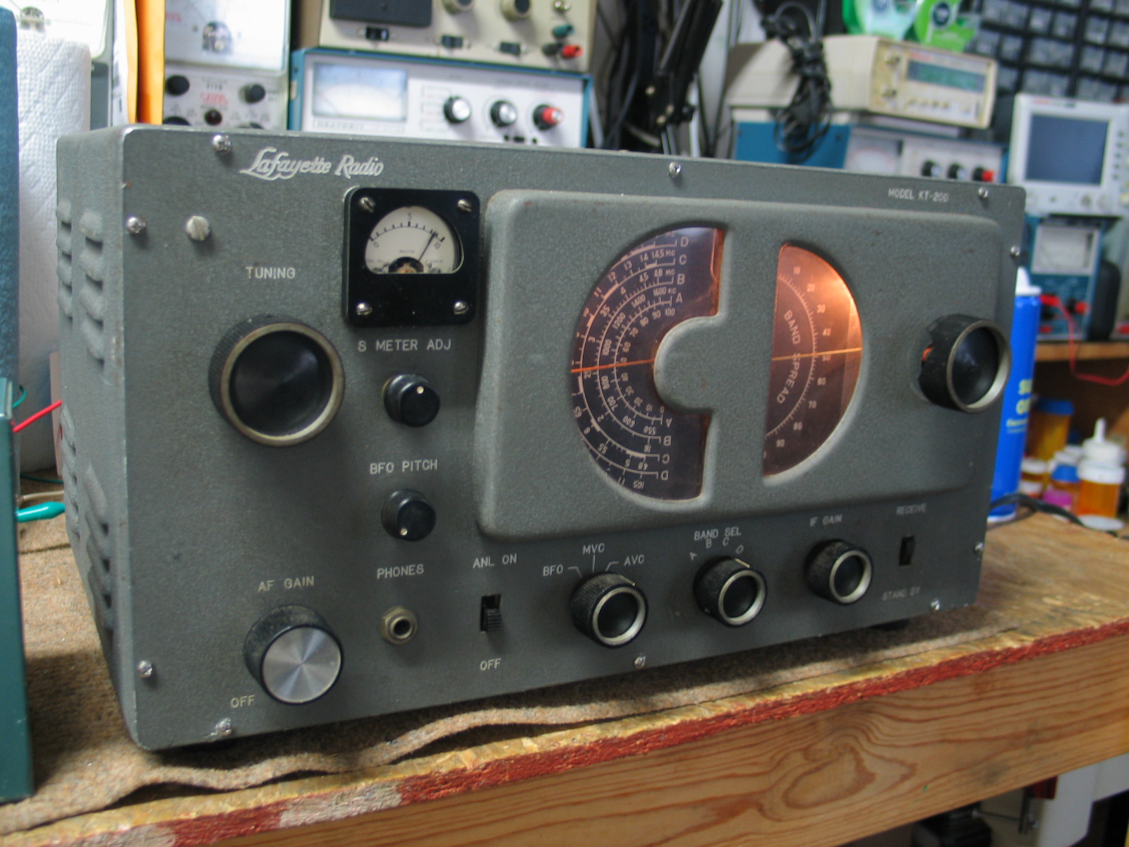
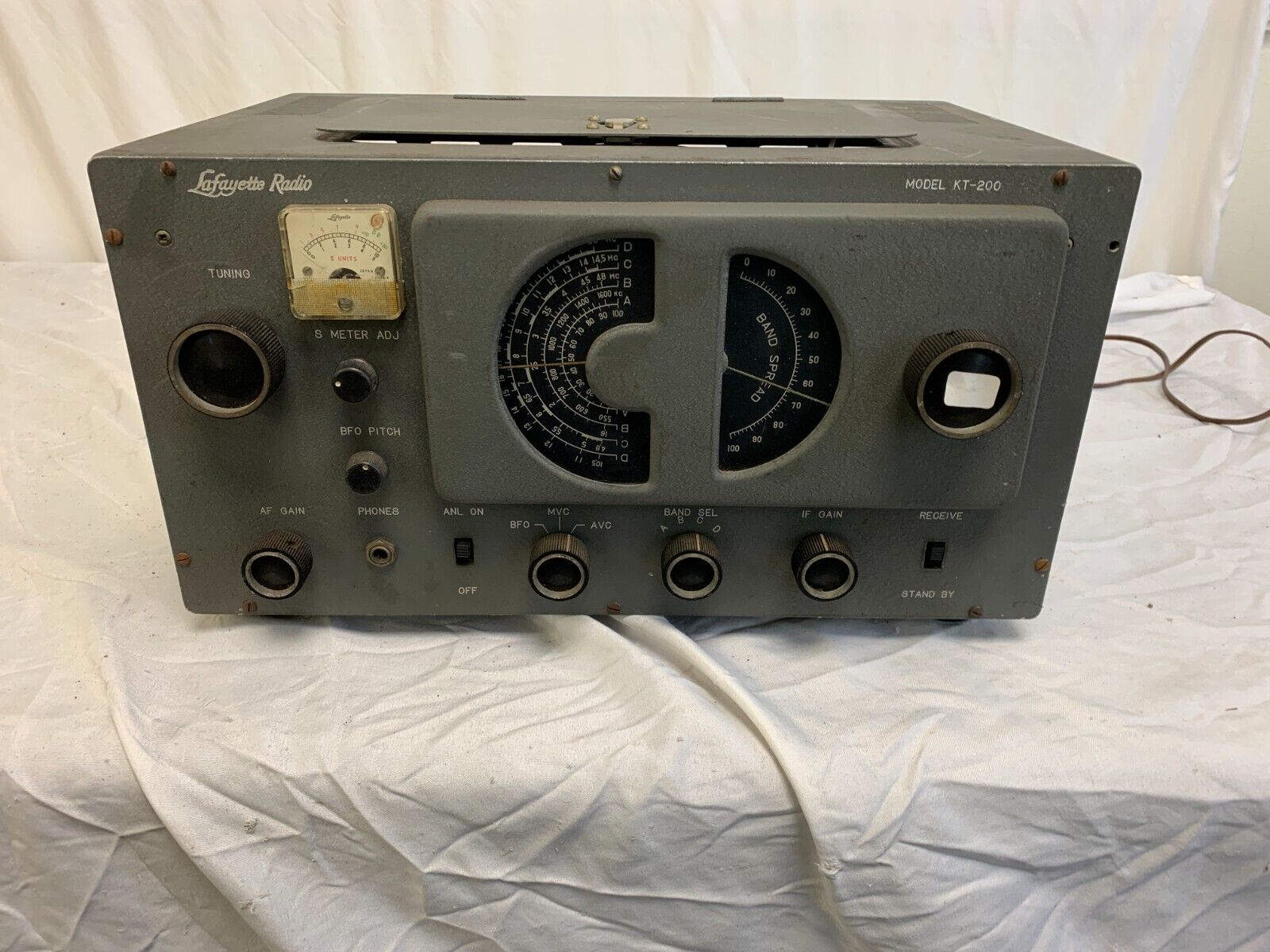
Front view
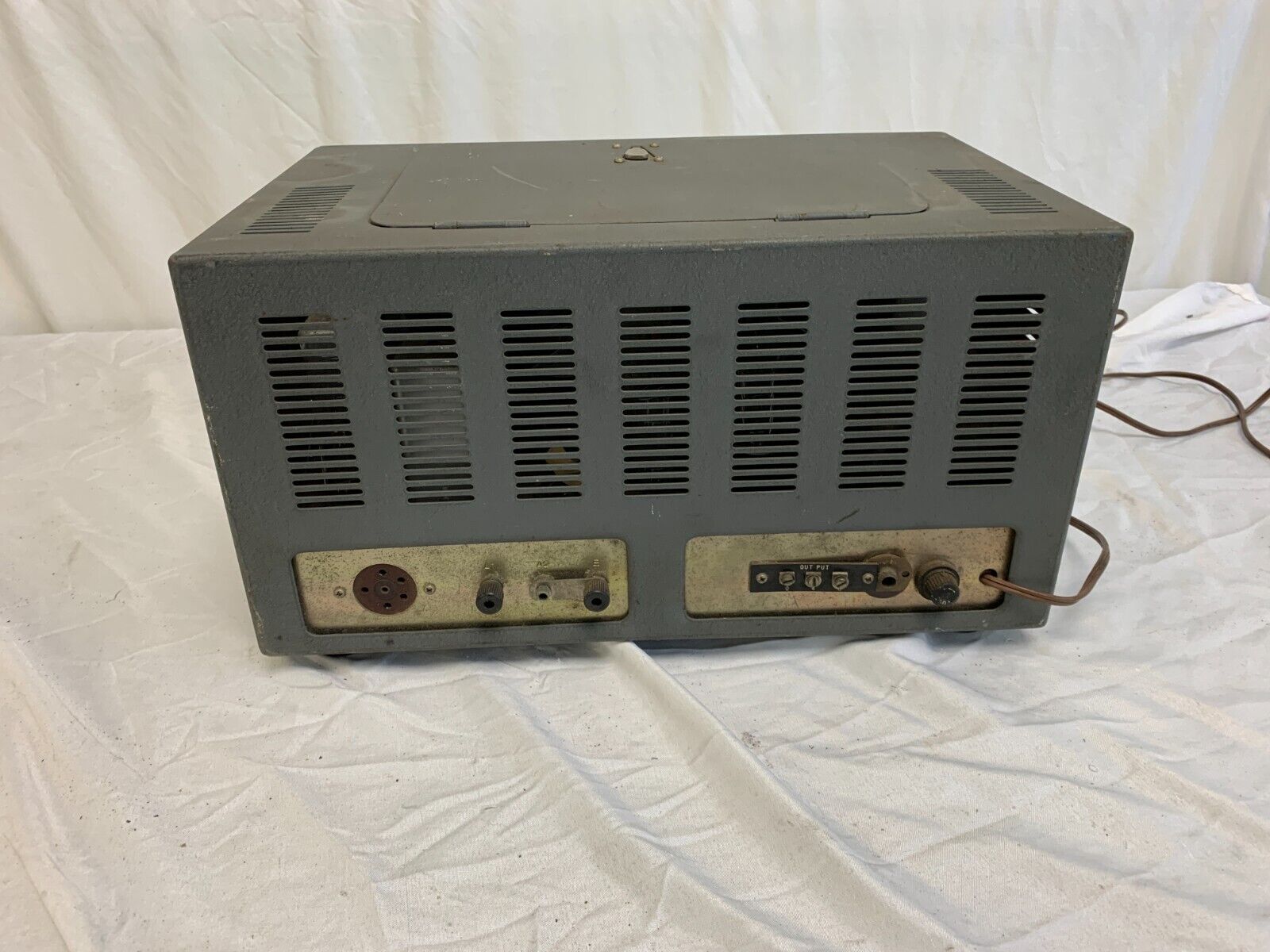
Rear View. Note RCA socket installed next to the 3 tab speaker terminal strip. Also note the broken/missing Banana antenna sockets .
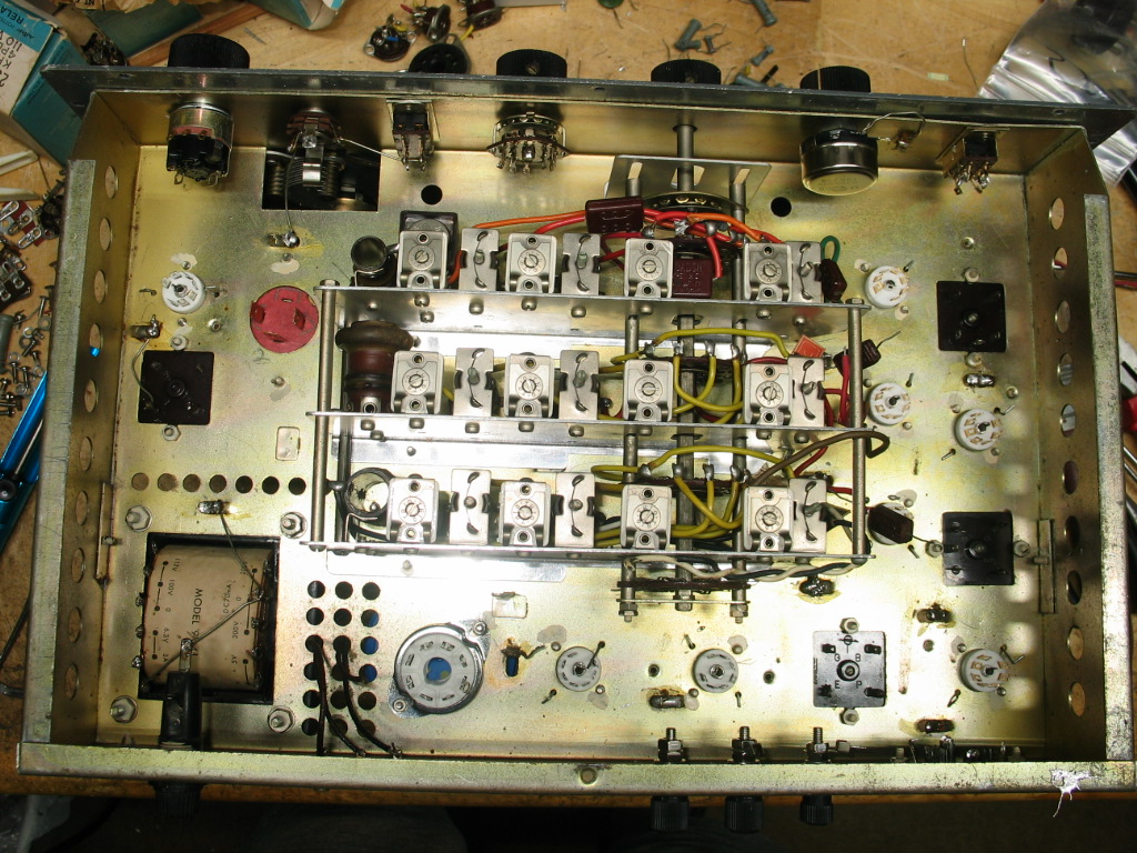
Top View showing all new tube sockets, replaced Banana antenna sockets, and fixed speaker connection.
Since this picture was taken I’ve removed all of the tube hold down wire clamps, they’re not needed. The audio transformer’s secondary wires are very thin as they leave the top of the transformer. I applied Gorilla Glue to the wires at the point where they exit the transformer cord to provide more support (not shown in this picture). The audio transformer leads are very thin. I was concerned they could break so I cut the wires shorter then added 22awg solid copper wires to strengthen the wires. I slid correct color heat shrink tubing over the wiring and slid the wires through the holes in the chassis (not shown in this picture).
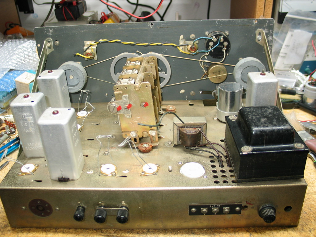
Bottom view showing full wiring and component disassembly. The original multi tab terminal strips were cleaned and reused (not shown in this picture). Front panel switches and headphone socket were cleaned of wiring and solder. I reused the original mounting hardware as it was in good condition.
There is an error on the second page of the assembly instructions. I’ve documented the error in the complete assembly manual. If interested in the error contact me for details. The band switch assembly in the middle of the chassis is the original design. The kit builder did not assemble the band switch assembly. The kit builder connected the band switch assembly to the rest of the wiring during the kit assembly.
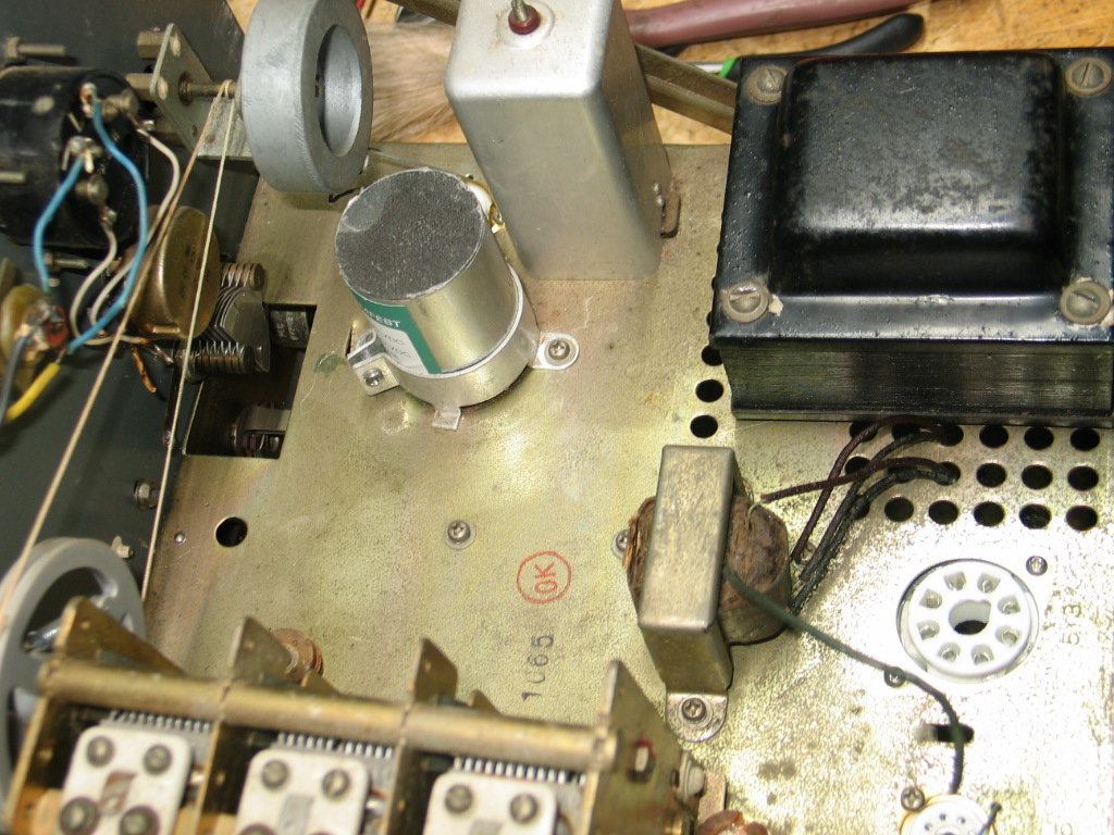
I could have used new individual 40ufd 350VDC axial lead capacitors to replace the original dual 40ufd capacitor but I wanted the rebuild to be as close to original as possible, so I special ordered a dual 40ufd 350VDC insulated power supply filter can capacitor from Hayseedhamfest.com including having the can capacitor wrapped in clear plastic just like the original can capacitor.
Update on point to point wiring
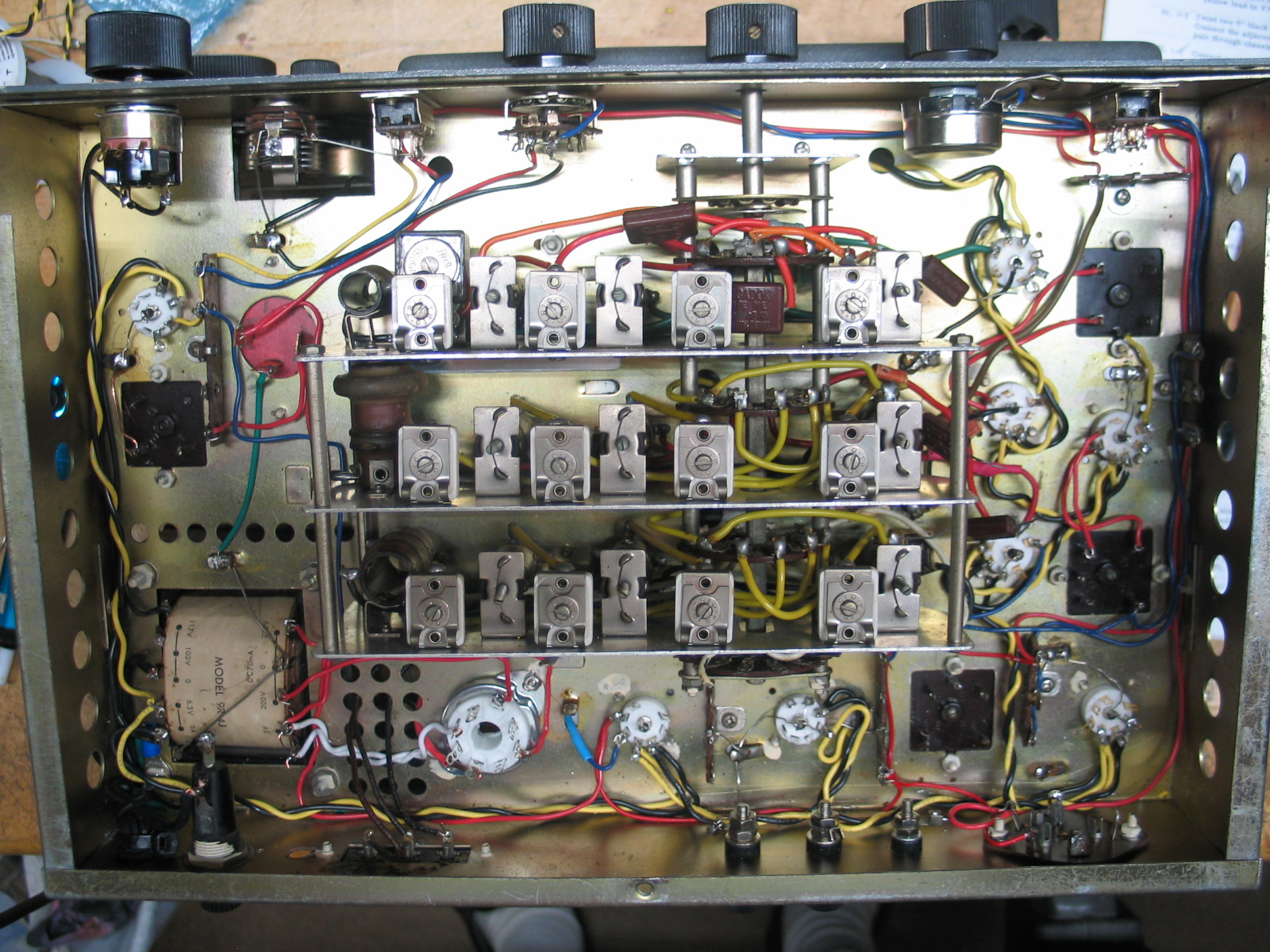
Point to Point Filament and B+ Wiring. Twisted Black and Yellow are the filament wires. Red is B+ wiring. I’m about 80% finished with the point to point wiring in this picture. There are 5 RG-174 coax cables that need to be installed.
Update on component wiring
I have 95% of the resistor and capacitor components installed in this picture. There is one and a half pages left to complete the assembly of the KT-200.
I was able to reuse some of the original resistors as I didn’t have those values in my new resistor part bins. I checked each original resistor to ensure it was within 10% tolerance. I was surprised, all of the original resistors I reused were all within “1%” of the resistor’s tolerance. The reused original resistors are Gray dog bone type resistors.
Click the picture to zoom in and out for a better close up viewing of the wiring.
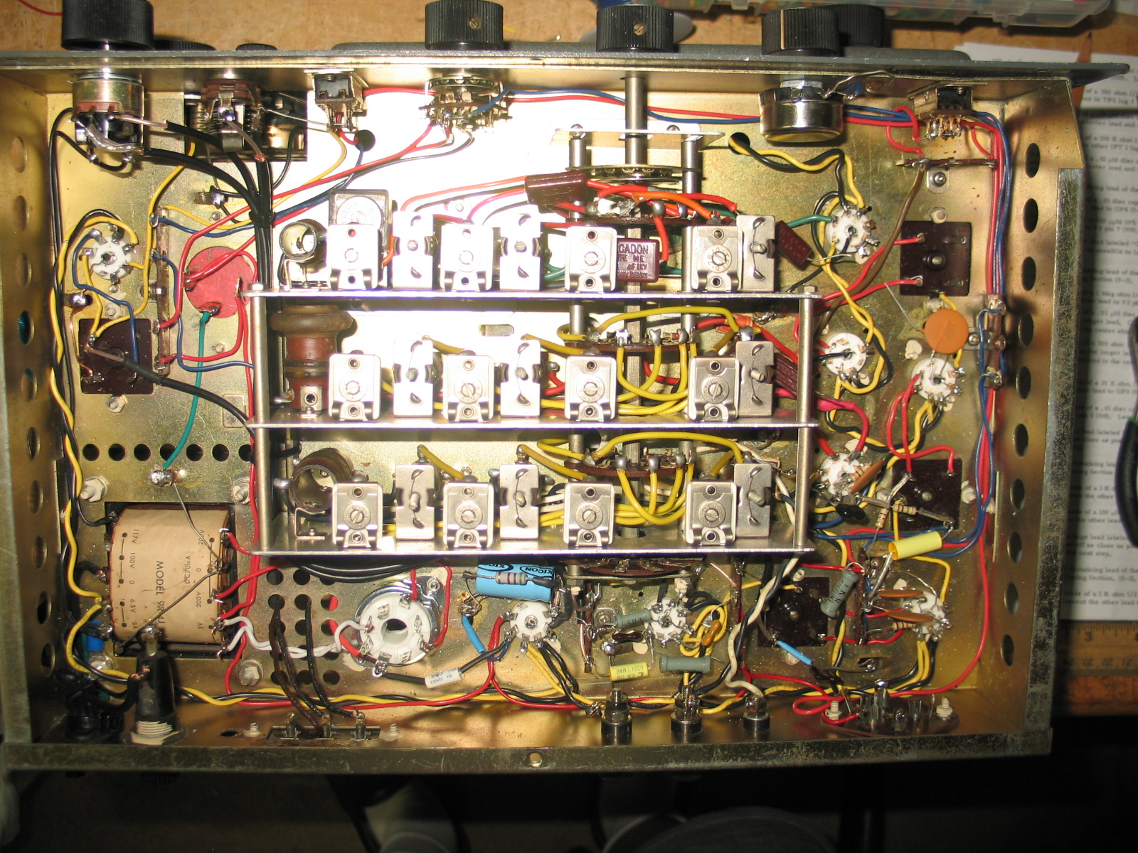
The 5 RG-174 coax cables have been installed, connected, and tie wrapped.
Full Rebuild Complete
12 Nov 2023
The full restoration reassembly of the Lafayette KT-200 receiver is complete. I use 90% new components and 10% original resistors as some of the resistor values are not easily available today. I verified each resistor, original and new, to ensure their values were correct.
The filament wiring is Black/Yellow 18awg solid copper wire. The other wiring is 22awg solid copper wire. The large Black resistor on the upper left is R21, a new 2K 10W. I did not use C24, a 0.01ufd 600VDC capacitor across the primary winding of the power transformer.
I performed the 2 preliminary resistance checks in the manual. I replaced the original 2 wire power cord with a 3 wire grounded power cord. The manual’s 2 resistance checks passed. I then performed a thorough visual inspection of all connections to ensure there were no shorted leads, bad soldering, and connections that did not have any solder. All soldering issues were fixed.
A 3/4 amp fast blow fuse was placed in the fuse holder.
Final power up test was successful. The receiver came to life and signals were heard on the various bands when an antenna was connected to the rear Banana sockets.
Click the link below to watch my video of the working fully restored Lafayette KT-200 4 band shortwave receiver.
Update on the S meter replacement
I was able to find a few R390 1ma FS meters that fit perfectly in the front panel opening. I settled on the White scale meter, looks closer to the original S meter. The meter does not have an S Unit scale but rather tick marks between 0, 5, and 10. I added dual back to back diodes across the meter terminals.
https://w5rkl.com/wp-content/uploads/2023/11/Fully-Restored-Lafayette-KT-200.wmv
The video link below was made with the dark scale R390 meter. The picture below shows a White scale R390 meter but I have since changed the meter to a Black scale R390 meter after the picture was taken. The meter is the same as the White scale meter but it has a Black scale.
The front view pictures were taken before the AF Gain control knob was replaced. The AF Gain control was replaced with a new control, the original was control was bad. The AF Gain control knob shown in the pictures has since been replaced with an original KT-200 knob.
Replacement meter using an R390 Meter