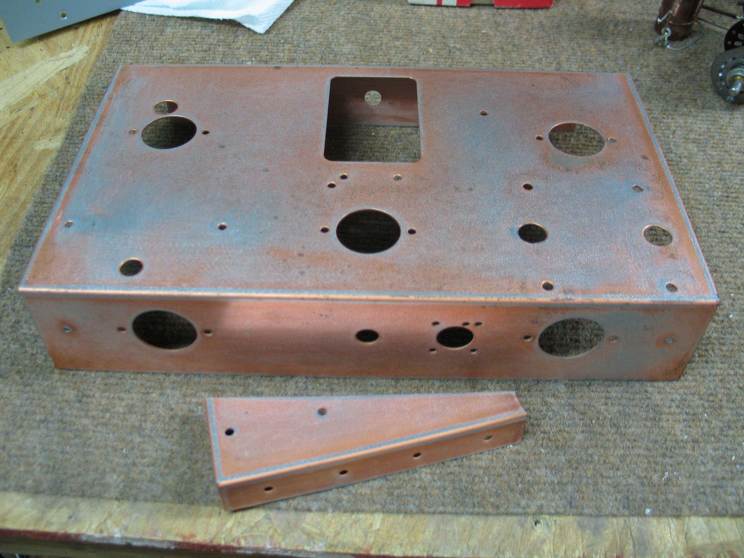
Before:
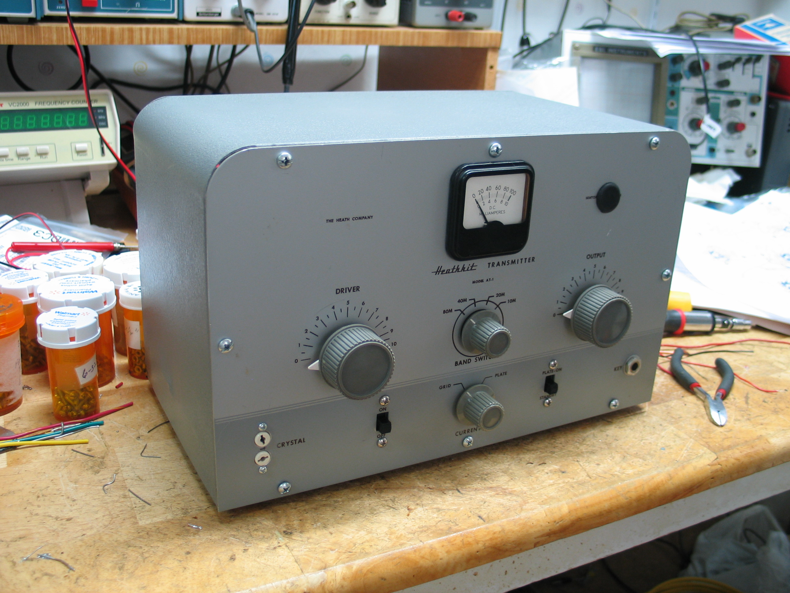
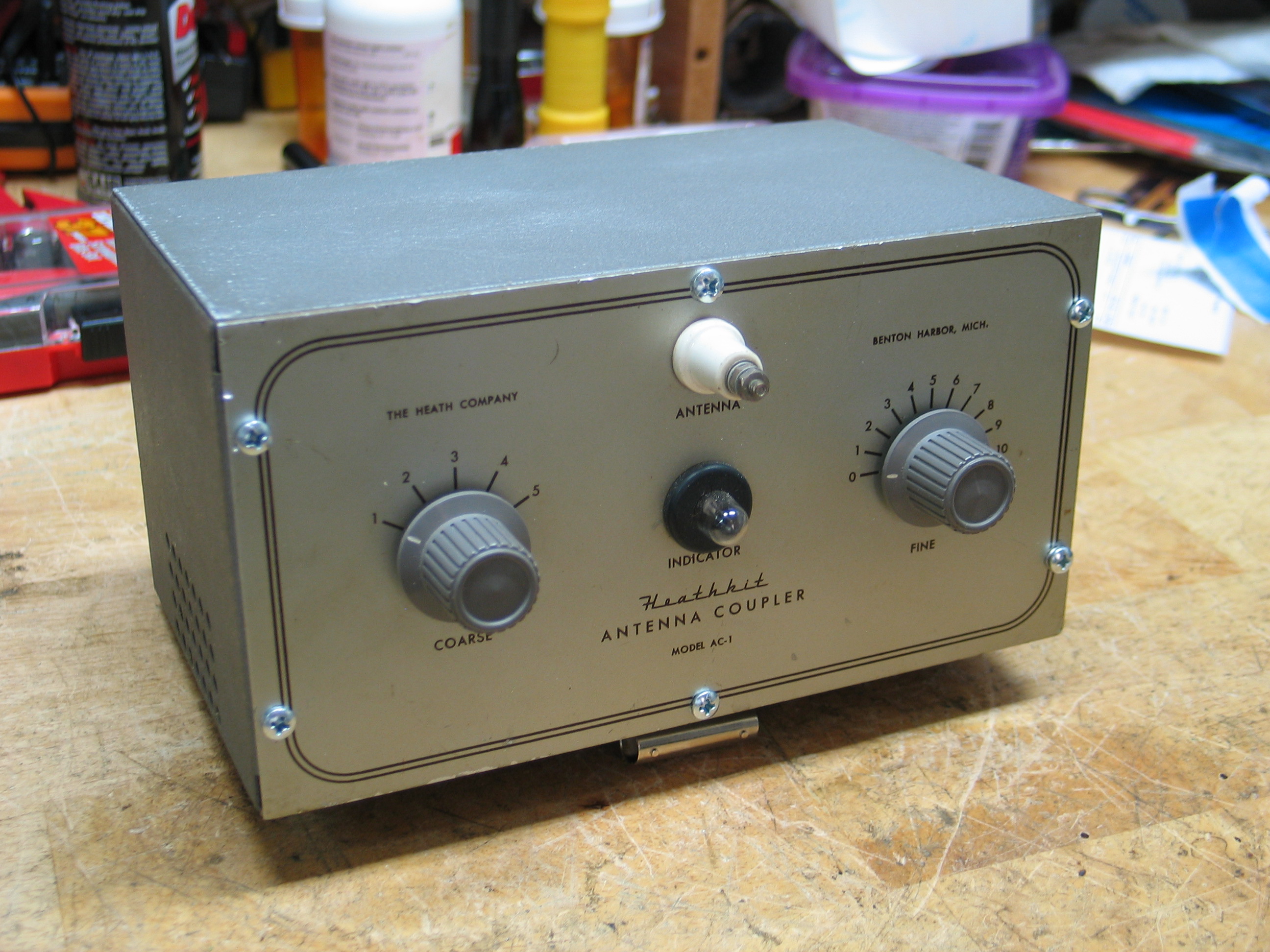
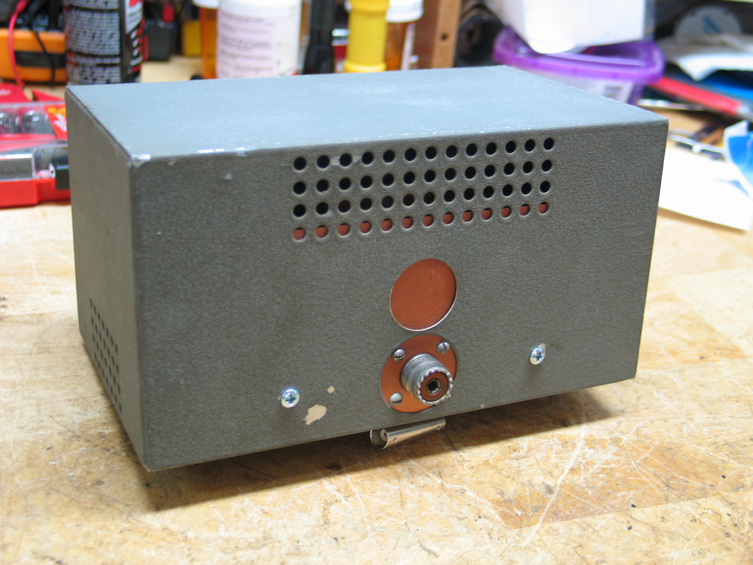
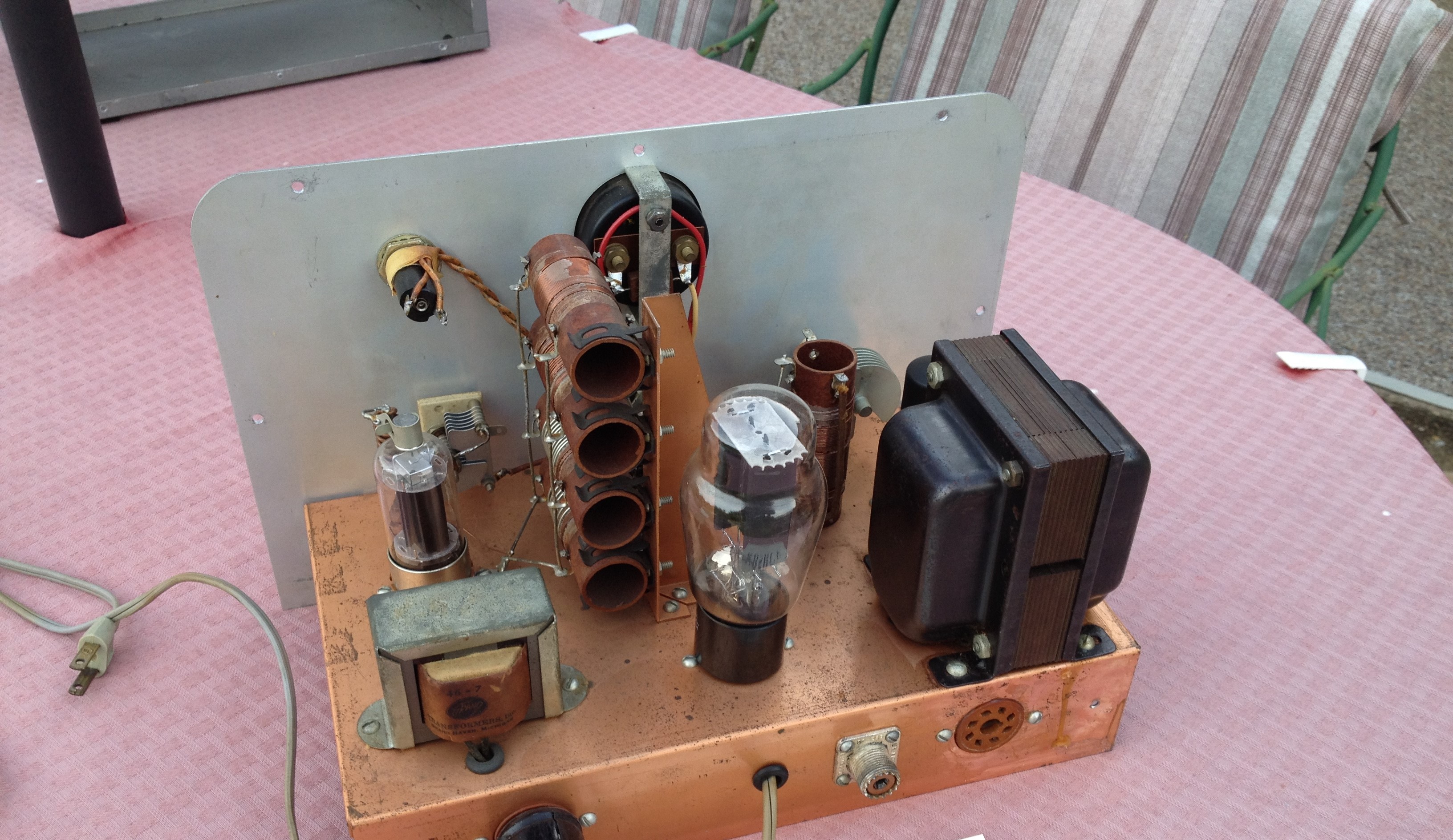
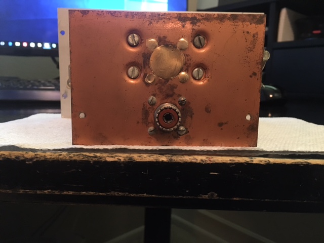
Note a previous owner changed the final from a 6L6 to a 2E26 and drilled a hole in the front panel to mount a power on indicator. The chassis is discolored due to aging and the AC1 rear panel had an additional hole large enough for a SO-239 socket. The filling of the hole is poor so a little work on the hole filling is needed. The power transformer has overheating problems so it will have to be rewound or replaced.
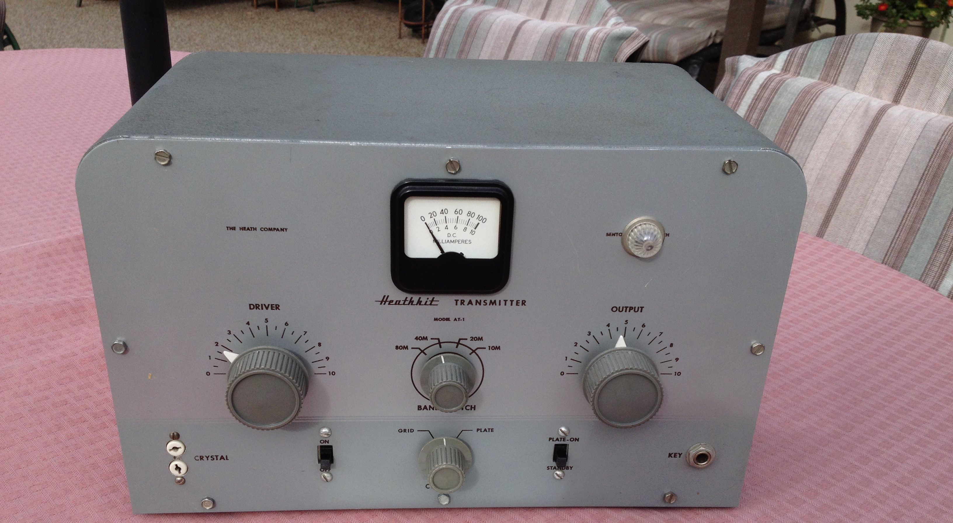
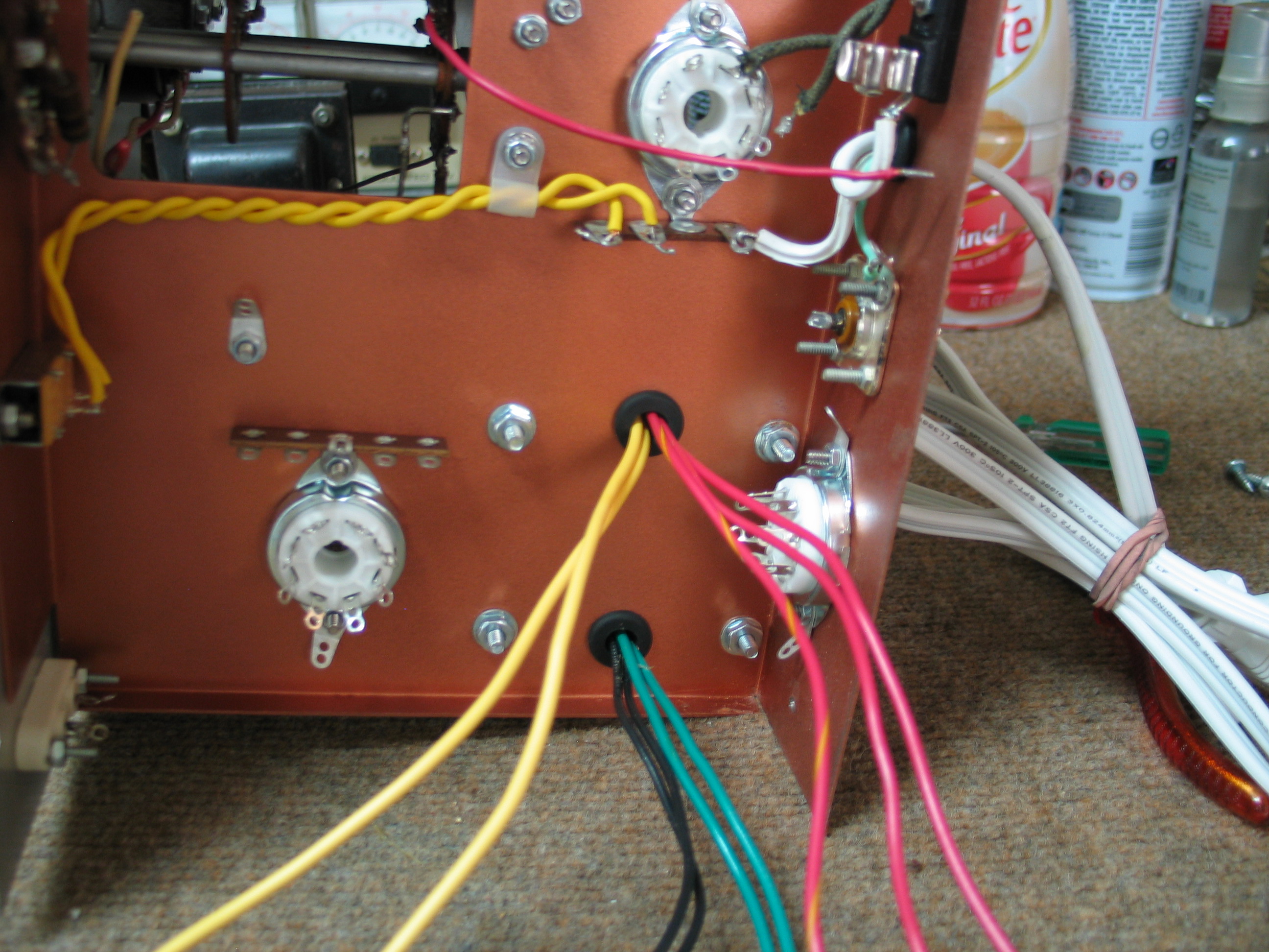
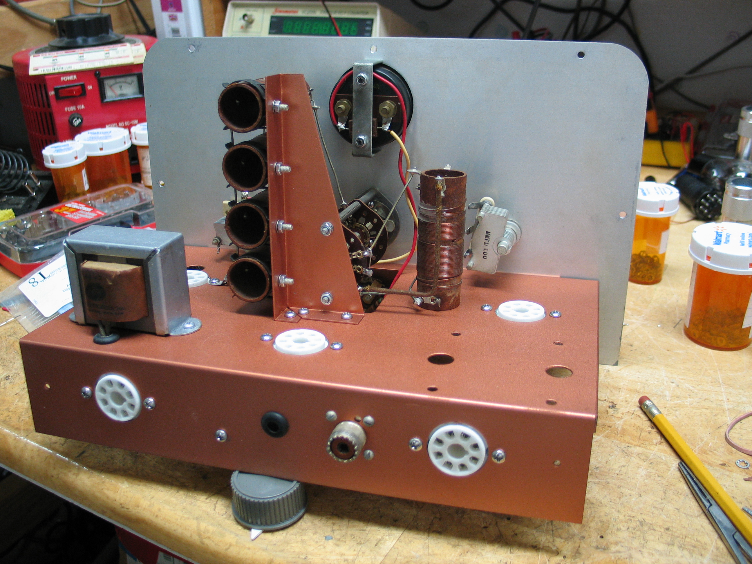
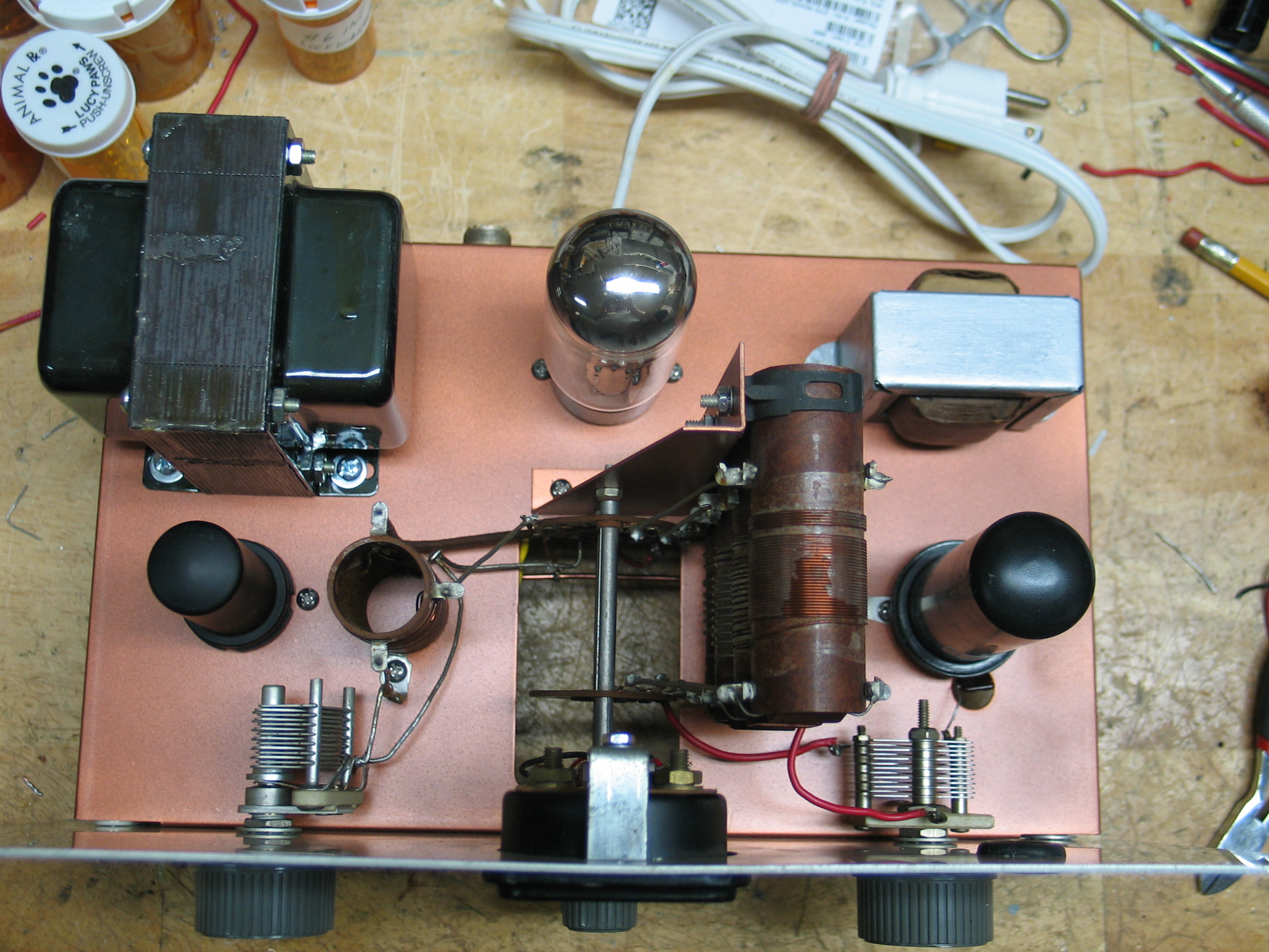
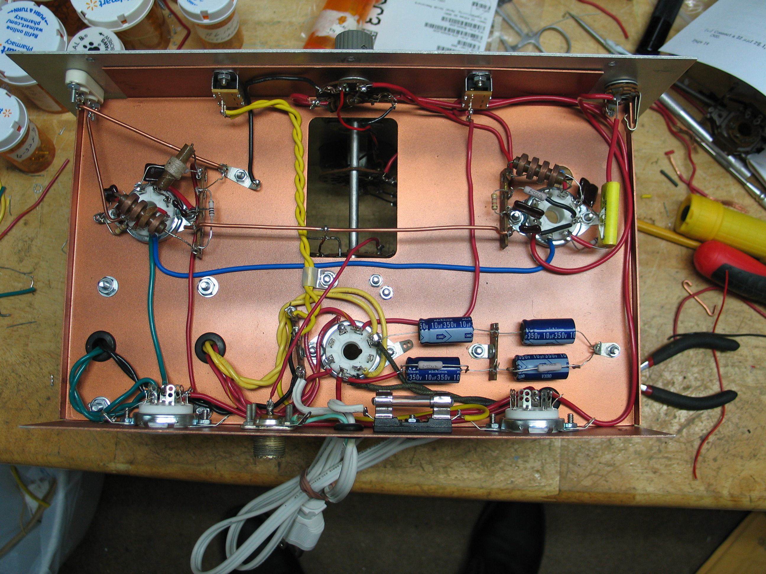
After:
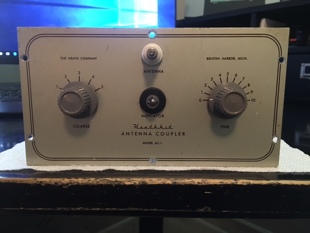
The chassis and mounting brackets were stripped of all components then sanded and painted Rustoleum Metallic Copper paint. New rubber grommets replaced all the old dried out and missing grommets. The point to point wiring was all removed and discarded. The fixed capacitors and resistors were replaced with new components. The power transformer was found to be bad so it was replaced with a NEW, not rewound, a transformer from Heyboer Transformers in Grand Haven Mich. The variable capacitors were thoroughly cleaned and lubricated. The 2E26 and wiring was replaced with the original 6L6 wiring. The wide bottle 5U4G is replaced with a slim 5U4G rectifier. All tube sockets were replaced new sockets, all mounting hardware was replaced with new mounting hardware, and point to point wiring is all new. The switches were thoroughly cleaned. The power indicator hole was filled with a rubber grommet. The cabinet was lightly sanded and painted light gray. The power cord was replaced with a polarized power cord and a fuse holder with the proper fuse was mounted below the chassis. The AC1 “extra hole” on the rear chassis was sanded smooth and the chassis was painted the same Rustoleum Metallic Copper paint. The transmitter was tested and found to produce approximately 12 watts output into a 50-ohm dummy load at 3.525Mhz crystal controlled. The Keying circuit was wired so both the oscillator and final amplifier are keyed. The keyed signal is clean and no chirp.